Archive for August 2016

The esp8266 and SD Cards

espusb1espusb2
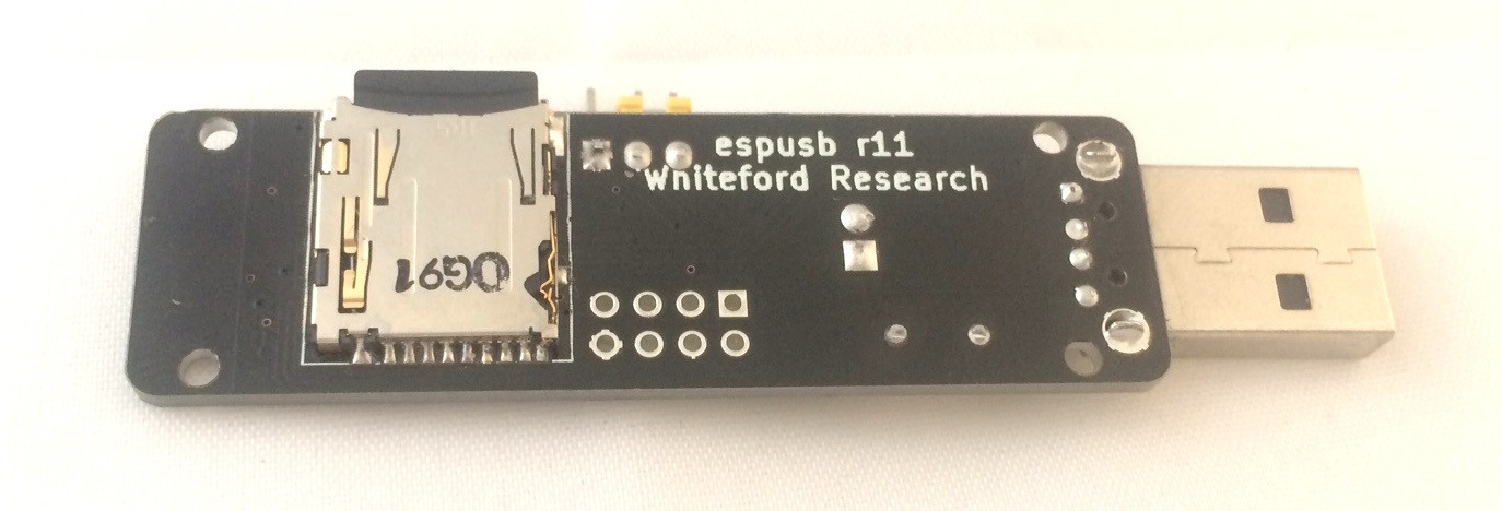
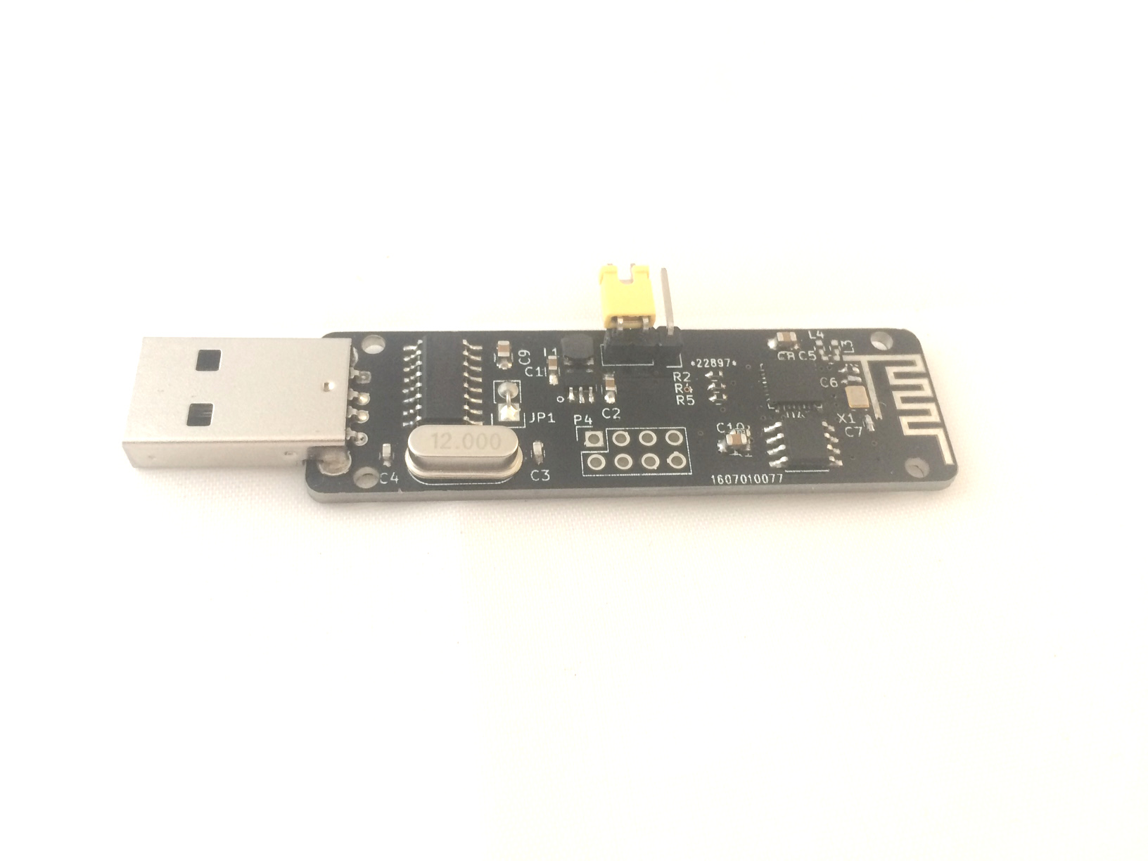
Recently I’ve been using the esp8266 with SD cards in order to develop the small board shown above and to the right. It hosts a CH340g USB interface, small buck converter to supply 3.3v to the esp8266 and an SD card slot.

The esp8266 is pretty thin, and doesn’t really give the information necessary to get up and running, so it took some research and hacking around to get everything working.

A lot of this was motivated by this forum thread which provided that it was possible to get SD cards working on the esp8266 using the SPI interface. SD cards generally use a more complex protocol and multiple data lines, but they can fall back to SPI mode (albeit with reduced performance).

The Arduino esp8266 support pack also has done great work, and after configuring a chip select pin, the SD card library supplied there pretty much just works.

I wanted to use the native esp8266 SDK without the Arduino environment. This took some hacking, but so far I’ve extracted the SD card library and have it up and running using a native SPI driver, the main issue was enabling (the again undocumented) duplex mode of the esp8266 SPI interface. If you’d like a copy of this code ping me.

One final note, some documents refer to “SD Card” boot mode. That would be really cool, to be able to load your firmware directly from an SD Card. Unfortunately it’s a bit of a misnomer. “SD Card” mode actually refers to SDIO mode. We don’t really hear much about SDIO anymore, but you used to be able to buy these funky Wifi cards which plugged into SD card slots. Other peripherals, like cameras were available too. You can read more about it on the wikipedia page.

The esp8266 supports an SDIO boot mode. My guess is that this is a hang over from its heritage as a general purpose Wifi interface chip. Some people have used this functionality to enable firmware loading over SPI. It’s neat, but unfortunately doesn’t mean you can boot from a standard flash SD card.

PLUG: I’m now selling the esp8266 SD card board above on my shop. My hope is to eventually progress this toward a consumer product which runs an access point and provides basic collaboration tools.

The CL0116 Solar Lantern Controller IC

solar_kit_assem

I’ve been playing with these simple Solar lantern controller ICs recently. They’re the chips used in most cheap solar garden lights. Akiba and I have built a couple of products around these chips and have more in the works.

They’re pretty amazing ICs given that they cost almost nothing and contain a complete NiMH charge controller, boost converter, and PWM LED driver.

sch_cl0116The basic circuit from the datasheet is shown to the left, and aside from the IC itself you just need to add a single inductor, NiMH battery, solar cell and of course the LEDs to complete the circuit.

It uses the solar cell both to charge the battery and as a light sensor. When voltage from the solar cell falls below 150mV the IC will switch into illumination mode and start powering the LEDs. Rather than a typical current limiting configuration, the IC slightly overdrives the LEDs but uses a 100KHz pulse-train to drive them which they suggest results in >90% efficiency.

Considering the IC basically costs nothing this is pretty impressive. I have a set of 10 ICs+inductors on my shop if anybody else wants to play with them.

FG-100 Soldering Iron Tip Temperature Sensor

fg100

I picked up this cheap soldering iron temperature sensor. I mostly wanted it to check the heat capacity of the various tips I have. I was disappointed that it came with Hakko branding, the supplier just listed it as an FG100 (which is a Hakko model number) but it’s clearly fake.

It does however work pretty well, and I was able to see clear differences between my T12-D12 (1.2mm) tip and T12-D24 (2.4mm). I’ll be performing further tests to see how well the various tips perform and see if I can more accurately gauge the heat capacity of the tips. I also want to use this to check the calibration of cheap Hakko 936 clones that I’ve been picking up from Shenzhen for running workshops.

bigtip_fg100

T12-D24 Tip

IMG_0660

T12-D12 Tip

It comes with a set of 10 K-type thermocouples, in order to insure good heat transfer the soldering iron tip should be wet with solder when you measure the temperature. This unfortunately means the thermocouple can get mucky pretty quickly which is why it’s a replaceable part.

Obviously I’ve also taken the device apart too. Below you can see a couple of pictures of the PCB. It uses a single sided PCB with a die on PCB blob. I’m guessing this is a generic temperature sensing IC.


It’s interesting that the PCB has a soldermask, this seems to be a more recent trend with these ultra-cheap single sided PCBs which are commonly used in toys and other low cost products. If you’d like to buy this, I have it in my shop, with the Hakko branding removed. By purchasing from me you support further hacks. In particular I think it’s likely that you add a calibration pot (VR1 on the silk) and fahrenheit mode for people of this disposition.

pcbpcb2

Fiddling with a cheap 5 port dumb switch to add VLANs/port mirroring

IMG_0640

I’ve been hacking away at this cheap Shenzhen switch. If you’re interested in hacking on it, you can buy the exact model on my shop here. This also helps fund these hacks.

I picked up this switch on eBay. The seller described it as a gigabit switch, however when I opened it up it contained a IP178GH which is a 10/100 switch on a chip. Some googling locates a pretty decent datasheet for this IC (local copy: IP178G_IC).

While it’s only a 10/100 switch the datasheet is pretty interesting and shows it contains a full management interface. While it contains VLAN and other functionality, I was particularly interested in the port mirroring, which comes in handy when debugging network traffic (port mirroring forwards all TX and RX traffic to another port on the switch where you can monitor it with a packet sniffer like wireshark).

The datasheet describes how the management interface can be used. There are 2 modes of operation. One is that configuration can be loaded from SPI flash. The board contains an unpopulated footprint for the SPI flash, and at some point I plan to try this out.

However there’s a second “Serial Management Interface” which allows the switch configuration to be changed on the fly from an external microcontroller. Conveniently the 2 pins required are broken out on the board:

ip178_pcb

It seems they are also 5v tolerant, which means we can just throw an Arduino at them and bit bang an interface. Here’s my rather messy setup:

IMG_0639

The interface is a pretty simple half-duplex serial interface. There’s a timing diagram in the datasheet, though I didn’t see any clear information about clock speed. I used a clock rate of about 1KHz which seemed to work (I honest didn’t read the datasheet in detail, full details might be there somewhere).

ip178gh_timing

It also contains a full description of the register configuration. As I was particularly interesting in the mirroring config, and the example below programs these registers, here it is:

mirroring

With this in hand I was able to program phy 20 registers 3 and 4 to enable port mirroring from port 0 to port 1 and confirm that this worked correctly. The hacky Arduino code I wrote the included below, you should attach the clock to pin 2, data to pin 3 and make sure the ground is correctly connected.

The code is a mess, but it might prove useful if you’re trying to replicate this work.

1
2
3
4
5
6
7
8
9
10
11
12
13
14
15
16
17
18
19
20
21
22
23
24
25
26
27
28
29
30
31
32
33
34
35
36
37
38
39
40
41
42
43
44
45
46
47
48
49
50
51
52
53
54
55
56
57
58
59
60
61
62
63
64
65
66
67
68
69
70
71
72
73
74
75
76
77
78
79
80
81
82
83
84
85
86
87
88
89
90
91
92
93
94
95
96
97
98
99
100
101
102
103
104
105
106
107
108
109
110
111
112
113
114
115
116
117
118
119
120
121
122
123
124
125
126
127
128
129
130
131
132
133
134
135
136
137
138
139
140
141
142
143
144
145
146
147
148
149
150
151
152
153
154
155
156
157
158
159
160
161
162
163
164
165
166
167
168
169
170
171
172
int clock_pin = 2;
int data_pin  = 3;
 
int width=100;
 
void setup() {
  pinMode(clock_pin, OUTPUT); // CLOCK
  pinMode( data_pin, OUTPUT); // DATA
}
 
int recv_one_bit() {
  //Serial.print("1r");
  int data=0;
  digitalWrite(clock_pin,0);
  delayMicroseconds(width);
  digitalWrite(clock_pin,1);
  delayMicroseconds(width/2);
  data = digitalRead(data_pin);
  delayMicroseconds(width/2);
  digitalWrite(clock_pin,0);
  return data;
}
 
void send_data_bit(int data) {
  //Serial.print("1s");
  digitalWrite(clock_pin,0);
  delayMicroseconds(width/2);
  digitalWrite(data_pin,data);
  delayMicroseconds(width/2);
  digitalWrite(clock_pin,1);
  delayMicroseconds(width);
  digitalWrite(clock_pin,0);
}
 
void outhigh() {
  pinMode(data_pin,OUTPUT);
  digitalWrite(data_pin,1);
  digitalWrite(clock_pin,0);
}
 
void send_data(uint32_t data,int len) {
 
  for(int32_t n=len-1;n>=0;n--) {
  //for(int32_t n=0;n<len;n) {
    if(data & ((uint32_t)1 << n)) {
      send_data_bit(1);
    } else {
      send_data_bit(0);
    }
  }
}
 
uint32_t recv_data(int len) {
 
  //Serial.print("len: ");
  //Serial.println(len,DEC);
  uint32_t datain = 0;
  for(int32_t n=(len-1);n>=0;n--) {
    //Serial.println(n);
    int d = recv_one_bit();
    if(d != 0) {
      datain = datain | (uint32_t)((uint32_t)1 << n);
     // Serial.println("h");
     // Serial.println(((uint32_t)1<<n),HEX);
      //Serial.println(datain,HEX);
    }
  }
  return datain;
}
 
uint32_t read_op(int phy,int reg) {
   
  pinMode(data_pin,OUTPUT);
  send_data_bit(1);
   
  send_data_bit(0);
  send_data_bit(1);
  send_data_bit(1);
  send_data_bit(0);
   
  //send_data(1,2); // start bits
  //send_data(2,2); // read operation
  send_data(phy,5);
  send_data(reg,5);
 
  pinMode(data_pin,INPUT);//INPUT_PULLUP
   
  uint32_t in;
  int inA = recv_one_bit(); // turn around
  //int inB = recv_one_bit(); // this should be required as per spec, but a bit gets missed if I use it.
   
  in = recv_data(16);
 
  Serial.println("ta bits:");
  Serial.println(inA);
  //Serial.println(inB);
 
  outhigh();
  //send_data_bit(1);
   
  return in;
}
 
 
void write_op(int phy,int reg,uint32_t data) {
   
  pinMode(data_pin,OUTPUT);
  send_data_bit(1);
 
  send_data_bit(0);
  send_data_bit(1);
  send_data_bit(0);
  send_data_bit(1);
         
  send_data(phy,5);
  send_data(reg,5);
   
  send_data_bit(1);
  send_data_bit(0);
//  send_data(2,2); // Turnaround
   
  send_data(data,16);
}
 
 
void loop()
{
  Serial.begin(115200);
   
  outhigh();
  delay(1000); // one second
   
  uint32_t data = read_op(20,3);
  Serial.print("Old Read3: ");
  Serial.println(data,HEX);
   
  data = read_op(20,4);
  Serial.print("Old Read4: ");
  Serial.println(data,HEX);
   
  //Port mirroring config sits in phy 20, regs 3 and 4.
  //The bit pattern is shown below. See the datasheet for further details.
  //15.......................0 
  //   enable, mode, res, mirrored port rx
  //3: 1,   11,00000,00000001
  //
  //   monitoring port, res, mirrored port tx
  //4: 001 ,00000,00000001 
   
  uint32_t reg3 = 0xE001;
  uint32_t reg4 = 0x2001;
   
  write_op(20,3,reg3);
  write_op(20,4,reg4);
  delay(1000); // one second
 
  data = read_op(20,1);
  Serial.print("1Read1: ");
  Serial.println(data,HEX);
 
  data = read_op(20,2);
  Serial.print("1Read2: ");
  Serial.println(data,HEX); 
 
  data = read_op(20,3);
  Serial.print("2Read3: ");
  Serial.println(data,HEX);
 
  data = read_op(20,4);
  Serial.print("2Read4: ");
  Serial.println(data,HEX);
}