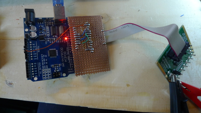
AD5791 20Bit DAC Evaluation board with Arduino
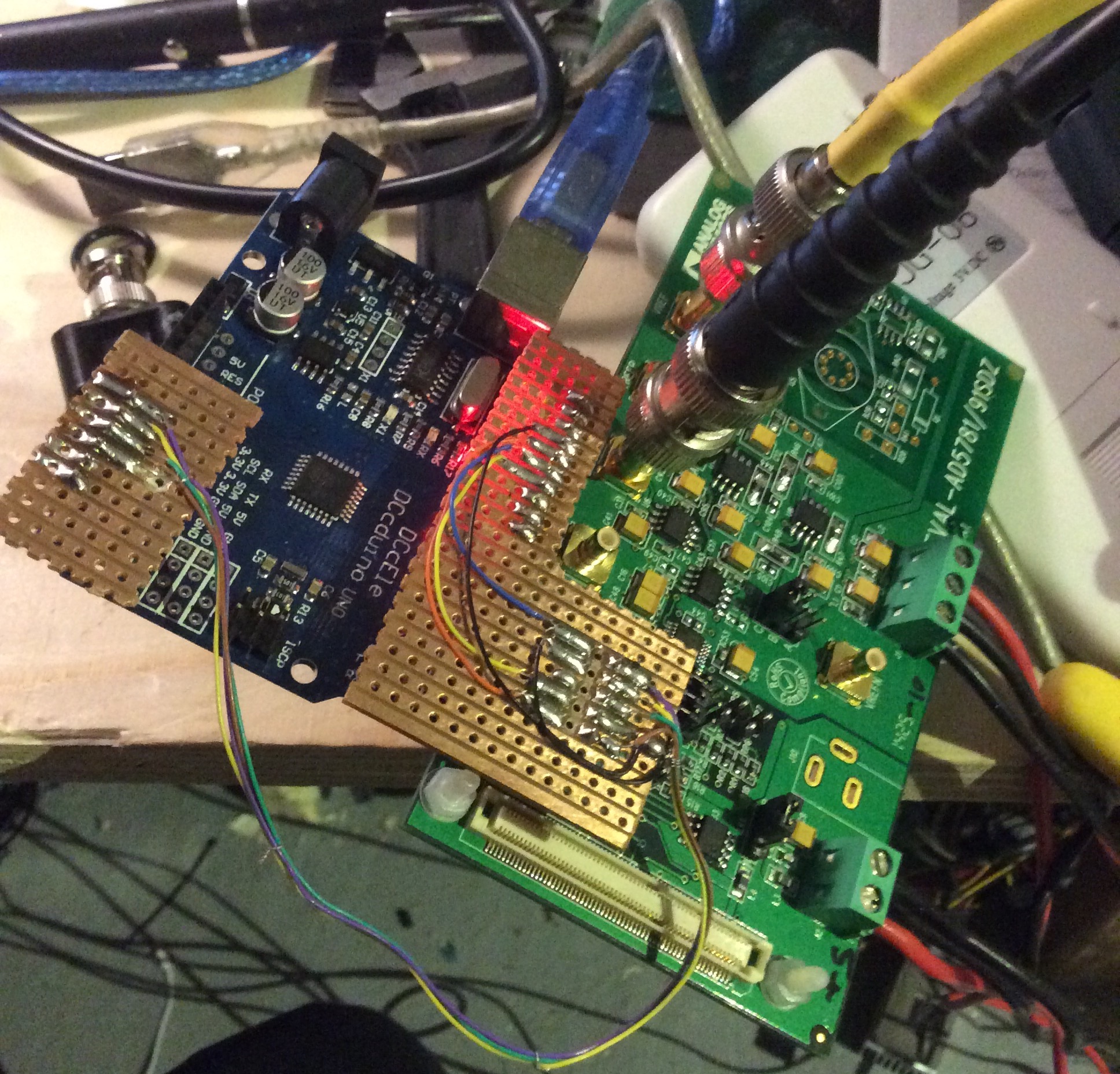
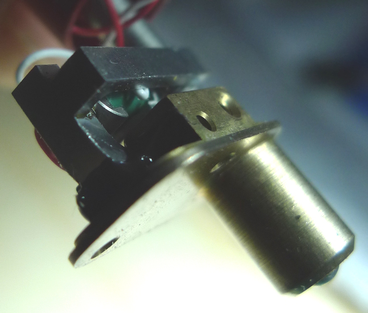
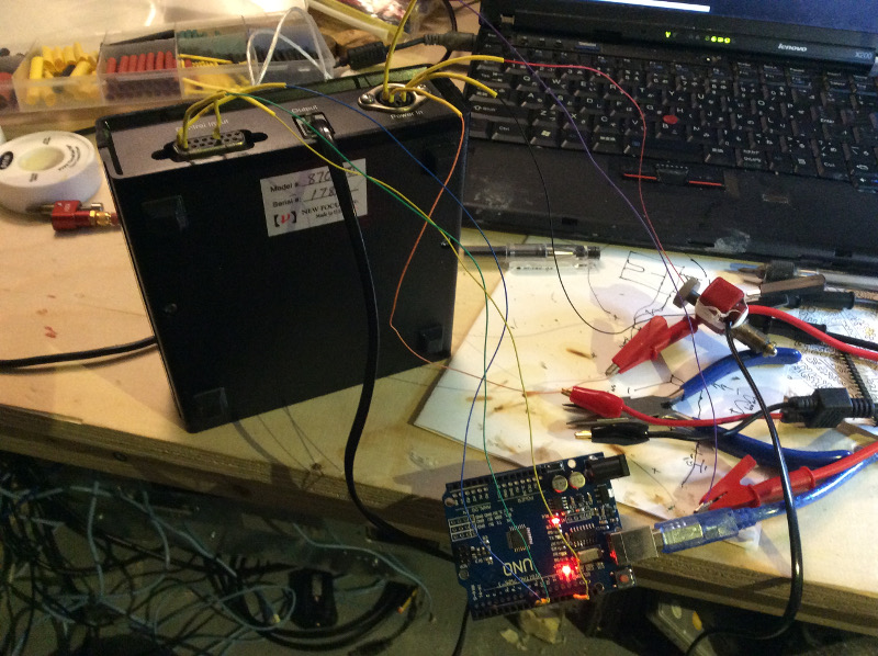
I’ve been playing with a 20bit DAC today. This is a precision DAC from Analog devices which is interfaced over SPI. There’s some non-Arduino example code on github here.
I hacked around with this so I could test the board on an Arduino. The code is below. Gotchas included: forgetting to connect the Voltage Reference!, not toggling LDAC to correctly, and not setting SPI MODE1. Lots of fun and games but it works now. The code below sweeps though all the output voltages. On my device this is going from +10 to -14V. I’ve still some debugging to do, it seems to sit at -14V for a while and I’m not sure why.
[UPDATE: this bug appears do be something to do with the negative voltage reference, selecting AGND on LNK9 (which uses AGND for the negative voltage reference) seems to sweep between 10 and -10 correctly).
#include <SPI.h>

const int reset = A0;
const int clr   = A1;
const int ldac  = A2;
const int sync  = A3;

void setup() {
  Serial.begin(9600);

  SPI.begin();


  pinMode(reset, OUTPUT);
  pinMode(clr  , OUTPUT);
  pinMode(ldac , OUTPUT);
  pinMode(sync , OUTPUT);
}

#define AD5791_NOP 0 // No operation (NOP).
#define AD5791_REG_DAC 1 // DAC register.
#define AD5791_REG_CTRL 2 // Control register.
#define AD5791_REG_CLR_CODE 3 // Clearcode register.
#define AD5791_CMD_WR_SOFT_CTRL 4 // Software control register(Write only).

typedef enum {
ID_AD5760,
ID_AD5780,
ID_AD5781,
ID_AD5790,
ID_AD5791,
} AD5791_type;

struct ad5791_chip_info {
unsigned int resolution;
};
static const struct ad5791_chip_info ad5791_chip_info[] = {
[ID_AD5760] = {
.resolution = 16,
},
[ID_AD5780] = {
.resolution = 18,
},
[ID_AD5781] = {
.resolution = 18,
},
[ID_AD5790] = {
.resolution = 20,
},
[ID_AD5791] = {
.resolution = 20,
}
};

AD5791_type act_device;

/* Maximum resolution */
#define MAX_RESOLUTION 20
/* Register Map */
#define AD5791_NOP 0 // No operation (NOP).
#define AD5791_REG_DAC 1 // DAC register.
#define AD5791_REG_CTRL 2 // Control register.
#define AD5791_REG_CLR_CODE 3 // Clearcode register.
#define AD5791_CMD_WR_SOFT_CTRL 4 // Software control register(Write only).
/* Input Shift Register bit definition. */
#define AD5791_READ (1ul << 23)
#define AD5791_WRITE (0ul << 23)
#define AD5791_ADDR_REG(x) (((unsigned long)(x) & 0x7) << 20)
/* Control Register bit Definition */
#define AD5791_CTRL_LINCOMP(x) (((x) & 0xF) << 6) // Linearity error compensation.
#define AD5791_CTRL_SDODIS (1 << 5) // SDO pin enable/disable control.
#define AD5791_CTRL_BIN2SC (1 << 4) // DAC register coding selection.
#define AD5791_CTRL_DACTRI (1 << 3) // DAC tristate control.
#define AD5791_CTRL_OPGND (1 << 2) // Output ground clamp control.
#define AD5791_CTRL_RBUF (1 << 1) // Output amplifier configuration control.
/* Software Control Register bit definition */
#define AD5791_SOFT_CTRL_RESET (1 << 2) // RESET function.
#define AD5791_SOFT_CTRL_CLR (1 << 1) // CLR function.
#define AD5791_SOFT_CTRL_LDAC (1 << 0) // LDAC function.
/* DAC OUTPUT STATES */
#define AD5791_OUT_NORMAL 0x0
#define AD5791_OUT_CLAMPED_6K 0x1
#define AD5791_OUT_TRISTATE 0x2

long AD5791_SetRegisterValue(unsigned char registerAddress, unsigned long registerValue) {
  unsigned char writeCommand[3] = {0, 0, 0};
  unsigned long spiWord = 0;
  char status = 0;
  spiWord = AD5791_WRITE | AD5791_ADDR_REG(registerAddress) | (registerValue & 0xFFFFF);
  writeCommand[0] = (spiWord >> 16) & 0x0000FF;
  writeCommand[1] = (spiWord >> 8 ) & 0x0000FF;
  writeCommand[2] = (spiWord >> 0 ) & 0x0000FF;

  digitalWrite(sync,LOW);
  status = SPI.transfer(writeCommand[0]);
  status = SPI.transfer(writeCommand[1]);
  status = SPI.transfer(writeCommand[2]);
  digitalWrite(sync,HIGH);

  return 0;
}

long AD5791_GetRegisterValue(unsigned char registerAddress) {
  unsigned char registerWord[3] = {0, 0, 0};
  unsigned long dataRead = 0x0;
  char status = 0;
  registerWord[0] = (AD5791_READ | AD5791_ADDR_REG(registerAddress)) >> 16;

  digitalWrite(sync,LOW);

  status = SPI.transfer(registerWord[0]);
  status = SPI.transfer(registerWord[1]);
  status = SPI.transfer(registerWord[2]);
  digitalWrite(sync,HIGH);


  registerWord[0] = 0x00;
  registerWord[1] = 0x00;
  registerWord[2] = 0x00;
    digitalWrite(sync,LOW);
  registerWord[0] = SPI.transfer(0x00);
  registerWord[1] = SPI.transfer(0x00);
  registerWord[2] = SPI.transfer(0x00);
    digitalWrite(sync,HIGH);
  dataRead = ((long)registerWord[0] << 16) |
             ((long)registerWord[1] << 8) |
             ((long)registerWord[2] << 0);
  return dataRead;
}

void loop() {

  // setup
  digitalWrite(ldac,HIGH);
  digitalWrite(reset,HIGH);
  digitalWrite(clr,HIGH);
  digitalWrite(sync,HIGH);
  SPI.beginTransaction(SPISettings(1000000, MSBFIRST, SPI_MODE1));

  long status = AD5791_GetRegisterValue(AD5791_REG_CTRL);

  status = AD5791_GetRegisterValue(AD5791_REG_CTRL);

  Serial.print(status,BIN);
  Serial.println();

  unsigned long oldCtrl = status;
  oldCtrl = oldCtrl & ~(AD5791_CTRL_LINCOMP(-1) | AD5791_CTRL_SDODIS | AD5791_CTRL_BIN2SC | AD5791_CTRL_RBUF | AD5791_CTRL_OPGND);

  status = AD5791_SetRegisterValue(AD5791_REG_CTRL, oldCtrl);

  status = AD5791_GetRegisterValue(AD5791_REG_CTRL);

  Serial.print(status,BIN);
  Serial.println();

  long d=100;
  for(long n=0;;n+=d) {
    // write DAC value
    //long int value = n;
    //value = value << (MAX_RESOLUTION - 20); // change for other devices in range

    digitalWrite(ldac,LOW);
    long v = n;
    status = AD5791_SetRegisterValue(AD5791_REG_DAC, v);

    //digitalWrite(ldac,HIGH);
    //Serial.print(n,BIN);
    //Serial.println();
    delay(1);
   if(n>= 524287) d=-100;
   if(n<=-524287) d=100;
   if(n%10000 == 0) Serial.println(n);
  }

}