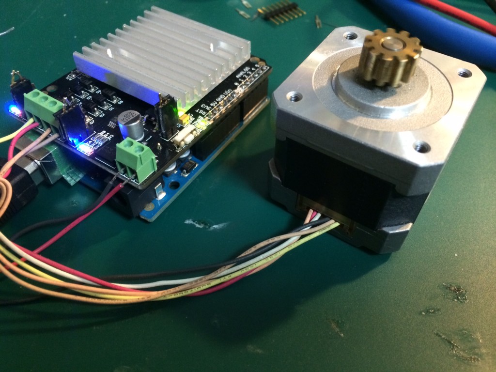
Stepper motors notes
Best Video I’ve seen on the basics of what’s going on in a stepper motor (he has a thick accent, but the content is great):
The take home message appears to be to understand how the poles are arranged such that the poles on the stator and electromagnets are offset slightly, so that with each step the rotor is pulled round.
After that it seems wise to investigate unipolar and bipolar configurations, as that will be one of the things you’ll encounter when setting up your steppers. As I understand it a unipolar motor uses two separate coils (or rather a single split coil, where only half is driven at any one time), and drives current in a single direction through each coil. A bipolar motor uses a single coil, the direction of the current is reversed to change polarity. Because unipolar motors just have an additional center tap, it is generally possible to drive them in both a unipolar, and bipolar configuration. Bipolar motors generally do not have a center tap, and therefore can not be driven as unipolar motors.
This is a pretty reasonable video on the topic:
As the strength of the magnetic field in an electromagnet is proportional to the current flowing through the coils, I would guess that you might want a driver that supplies constant current. However, a constant voltage over the winding resistance will give you a constant current in any case. The wikipedia page has some useful info here, the relevant part is replicated below:.
L/R driver circuits
L/R driver circuits are also referred to as constant voltage drives because a constant positive or negative voltage is applied to each winding to set the step positions. However, it is winding current, not voltage that applies torque to the stepper motor shaft. The current I in each winding is related to the applied voltage V by the winding inductance L and the winding resistance R. The resistance R determines the maximum current according to Ohm’s law I=V/R. The inductance L determines the maximum rate of change of the current in the winding according to the formula for an inductor dI/dt = V/L. Thus when controlled by an L/R drive, the maximum speed of a stepper motor is limited by its inductance since at some speed, the voltage U will be changing faster than the current I can keep up. In simple terms the rate of change of current is L / R (e.g. a 10 mH inductance with 2 ohms resistance will take 5 ms to reach approx 2/3 of maximum torque or around 24 ms to reach 99% of max torque). To obtain high torque at high speeds requires a large drive voltage with a low resistance and low inductance.
With an L/R drive it is possible to control a low voltage resistive motor with a higher voltage drive simply by adding an external resistor in series with each winding. This will waste power in the resistors, and generate heat. It is therefore considered a low performing option, albeit simple and cheap.
Chopper drive circuits
Chopper drive circuits are referred to as constant current drives because they generate a somewhat constant current in each winding rather than applying a constant voltage. On each new step, a very high voltage is applied to the winding initially. This causes the current in the winding to rise quickly since dI/dt = V/L where V is very large. The current in each winding is monitored by the controller, usually by measuring the voltage across a small sense resistor in series with each winding. When the current exceeds a specified current limit, the voltage is turned off or “chopped”, typically using power transistors. When the winding current drops below the specified limit, the voltage is turned on again. In this way, the current is held relatively constant for a particular step position. This requires additional electronics to sense winding currents, and control the switching, but it allows stepper motors to be driven with higher torque at higher speeds than L/R drives. Integrated electronics for this purpose are widely available.
This video on driving steppers in also interesting:
