NPN BJT Common emitter inverting amplifier
The Phase-Shift Oscillator I previously described used an NPN transistor as an inverting amplifier.
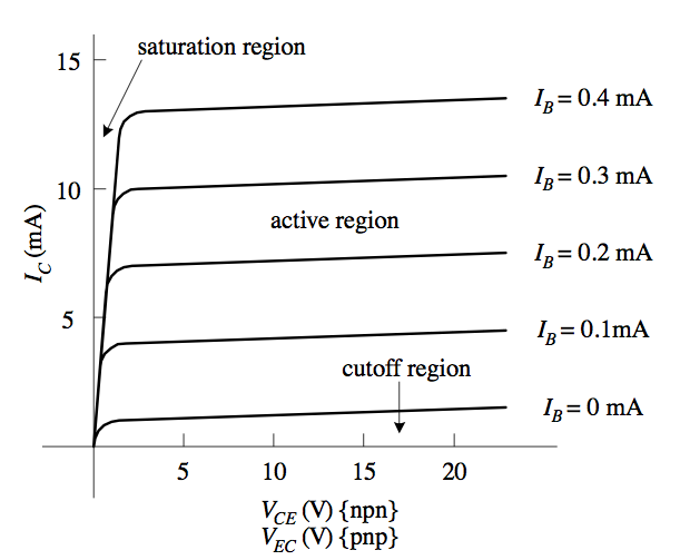
Transistors are current controller, current amplifiers. This means they take a control current in, and this is used to produce an output current. You’ll typically see curves like this used to describe the operation of a transistor:
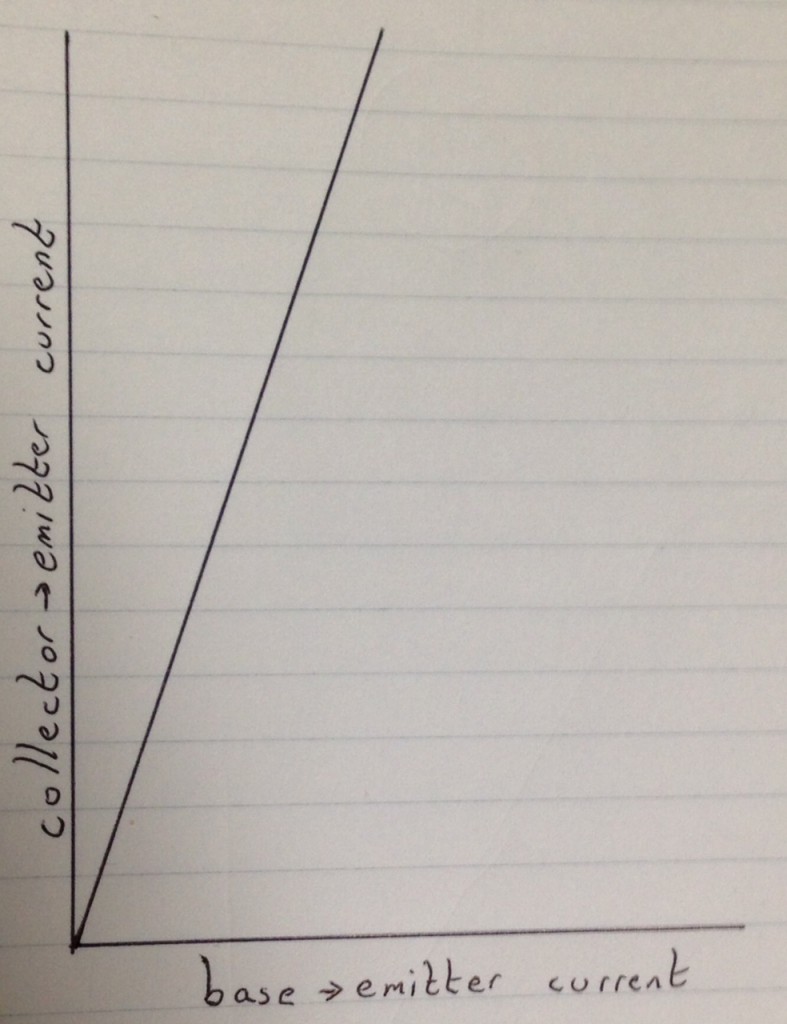
I find them pretty confusing as a first introduction to transistors. Most datasheets don’t seem to include these curves either. Here’s a simpler graph:
Not a very complicated graph is it. X any Y are on the same scale, so what the graph is saying is that a small change in the base->emitter current, creates a large change is the collector to emitter current. Let’s try and understand that in terms of resistance:
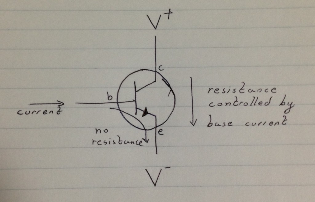
One way of thinking about a Bipolar transistor is as a electrically controlled variable resistor. By controlling the base current, you can control the resistance between the collector and emitter. But you generally aren’t using a current to control things in a circuit. This poses some practical problems. Let’s look at a 2N2222. You can download the datasheet here.
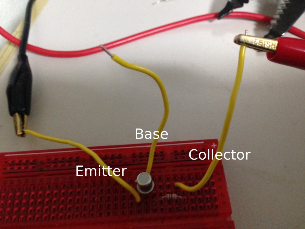
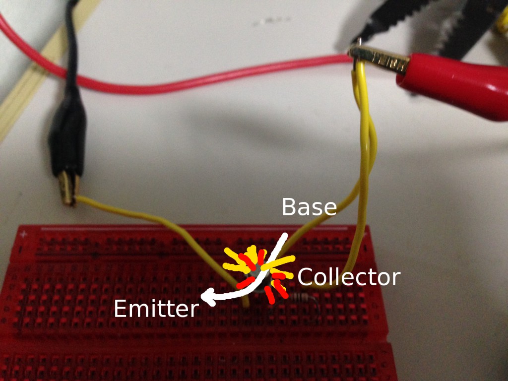
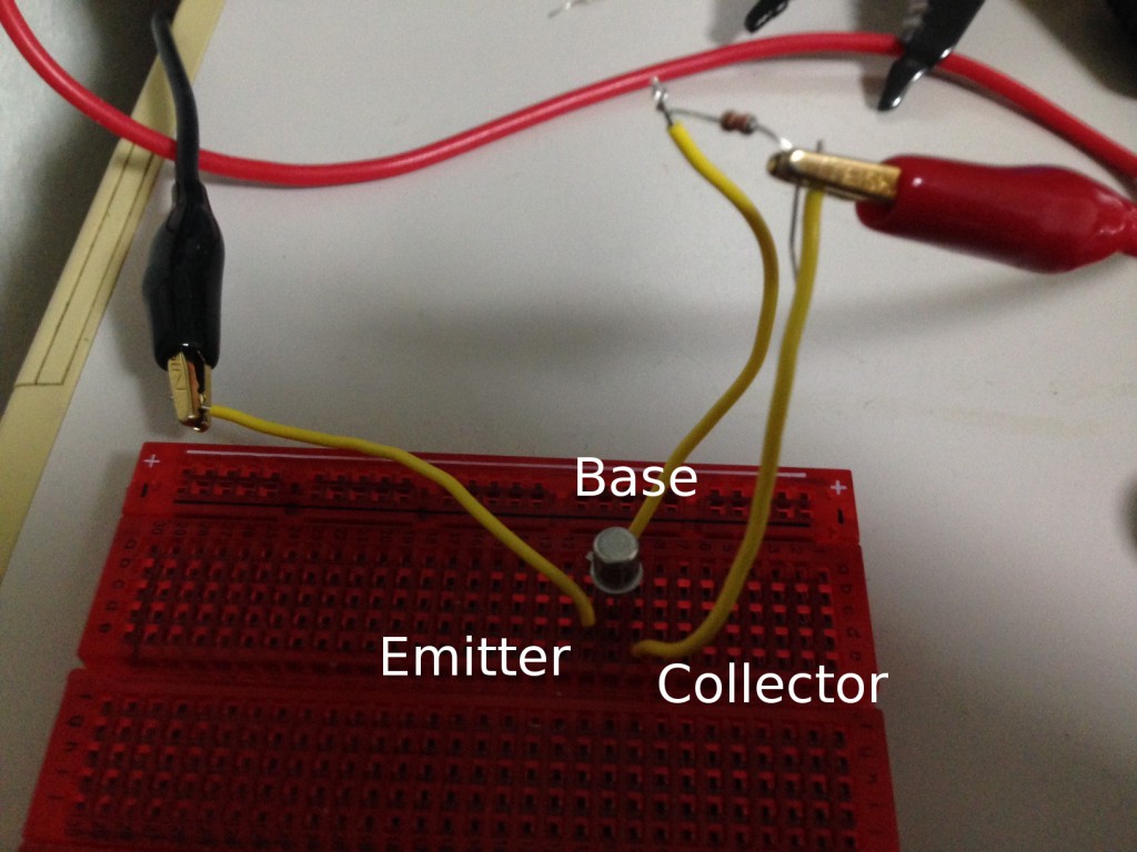
We can connected this up as follows:
The collector is connected to the positive supply, the emitter is connected to ground. No current will flow. I set the supply to 3 volts, and no current was being drawn.
So, let’s try connecting the base to the voltage source:
BANG! This wont work, there’s a current limiting resistor on the collector. So the reason isn’t that all the current flows from the collector to the emitter. No, the connection between the base and the emitter is the problem. Bipolar transistors are current controlled, and there’s effectively no resistance from the base and the emitter (as an analogy). This means that if we connect the base directly to a voltage source it will draw as much current as it can and the transistor will pop under the load.
The easiest way to limit the current supplied with a voltage source is with a resistor. I added a 220Ohm resistor to the base, over 3Volts (V=IR) this gives a base->emitter current of 0.01A. Note in the above circuit there’s no resistor on the collector. But the supply showed 460mA being drawn. From this we can calculate the “current gain”. 0.01A on the base = 0.46A on the collector. Which is a gain of 46. If we look at the datasheet:
We can see that’s about right, at a Collector current (Ic) of 440mA and around 1 to 10V we’re looking at a gain of 40 to 50. These results will hold as you vary the supply voltage, however you can’t go below 0.6V. The datasheet tells you this here:
So now we’ve seen how a transistor works. We’ve also seen how a voltage can be used to control the current flowing through the device. We can think of this as a current controlled variable resistor.
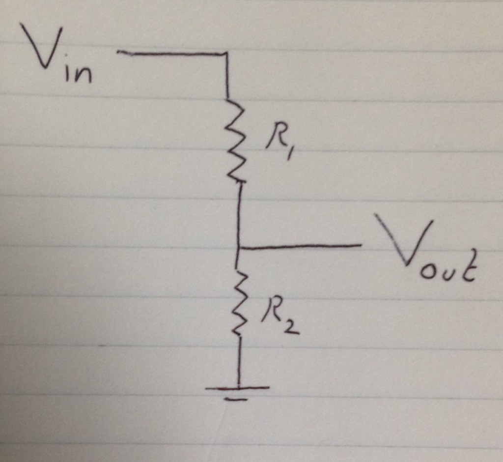
Well, a voltage divider looks like this:
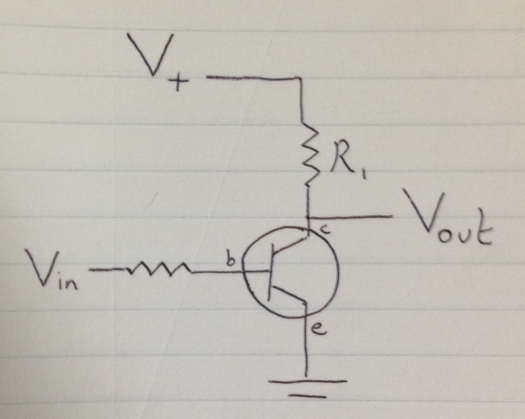
Voltage dividers let us create a smaller voltage from a larger one. The smaller R2, the smaller the output voltage will be. We can therefore replace R2 with a transistor and the control a large voltage with a smaller one:
There’s one caveat. As we increase Vin, more current will pass though the transistor from the collector to the emitter. We’re effectively decreasing the resistance, meaning Vout will also get smaller. This means we have an inverting amplifier. The larger the input voltage, the smaller the output voltage.
There are reasons we might often prefer this over a non-inverting configuration (replacing R1 with a transistor). The most significant being that as we saw above the transistor can’t operate below 0.6V. By working in an inverting configuration we can avoid that issue.
