January 20, 2015, 9:45 pm
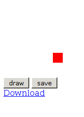
This following short example creates an canvas image using FabricJS. Pressing the draw, then save button creates an SVG representing this image, then creates a file based on this image using session local storage. Finally it adds a download link to this file to the html. The user can then download the SVG file to local storage. This has only been tested on Firefox.
UPDATE: FabricJS 1.4.0 appears to have issues where line coordinates get randomly offset. I’ve updated the example below to link to 1.4.13, however 1.4.0 is still linked as the latest CDN version on the FabricJS site. The example below will work with 1.4.0, but I don’t recommend using it.
<html>

<script src="http://cdnjs.cloudflare.com/ajax/libs/fabric.js/1.4.13/fabric.min.js"></script>
<script langauge="javascript">

  var m_canvas;

  function do_draw() {
    // create a wrapper around native canvas element (with id="c")
    m_canvas = new fabric.Canvas('c');

    // create a rectangle object
    var rect = new fabric.Rect({
      left: 100,
      top: 100,
      fill: 'red',
      width: 20,
      height: 20
    });

    // "add" rectangle onto canvas
    m_canvas.add(rect);
  }

  function do_save() {
    var filedata=m_canvas.toSVG(); // the SVG file is now in filedata

    var locfile = new Blob([filedata], {type: "image/svg+xml;charset=utf-8"});
    var locfilesrc = URL.createObjectURL(locfile);//mylocfile);

    var dwn = document.getElementById('dwn');
    dwn.innerHTML = "<a href=" + locfilesrc + " download='mysvg.svg'>Download</a>";
  }
</script>

<body>

<canvas id='c'></canvas>
<input type="button" id="drawBtn" value="draw" onclick="do_draw()"></input>

<input type="button" id="saveBtn" value="save" onclick="do_save()"></input>
<div id='dwn'></div>

</body>
</html>
January 20, 2015, 9:13 pm
I’m no JS coder, but for my reference below is a simple example showing how to create an SVG image in Javascript. The code below also shows how the SVG element itself might be created in JS.
UPDATE: If you’re looking at creating SVGs in Javascript, I recommend checking out FabricJS, I found it much easier to get what I wanted working.
<html>

<body>
<script language="javascript">

var svgNS = "http://www.w3.org/2000/svg";

function do_draw() {

  // The following commands can be used to create an SVG programatically
  // var mySVG = document.createElementNS("http://www.w3.org/2000/svg", "svg");
  // mySVG.setAttribute("height",300);
  // mySVG.setAttribute("width" ,300);
  // document.body.appendChild(mySVG);

  var mySVG = document.getElementById('mySVG')

  var circles = document.createElementNS("http://www.w3.org/2000/svg", "circle");
  circles.setAttribute("cx",20);
  circles.setAttribute("cy",20);
  circles.setAttribute("r",20);
  mySVG.appendChild(circles);
}

</script>


<svg id="mySVG" style="width:300px; height:300px" xmlns="http://www.w3.org/2000/svg" xmlns:xlink="http://www.w3.org/1999/xlink"/>
<input type="button" id="drawBtn" value="draw" onclick="do_draw()"></input><br><br>
<div id='main'></div>

</body>

</html>
January 18, 2015, 9:14 pm
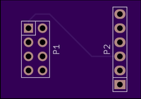
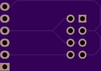
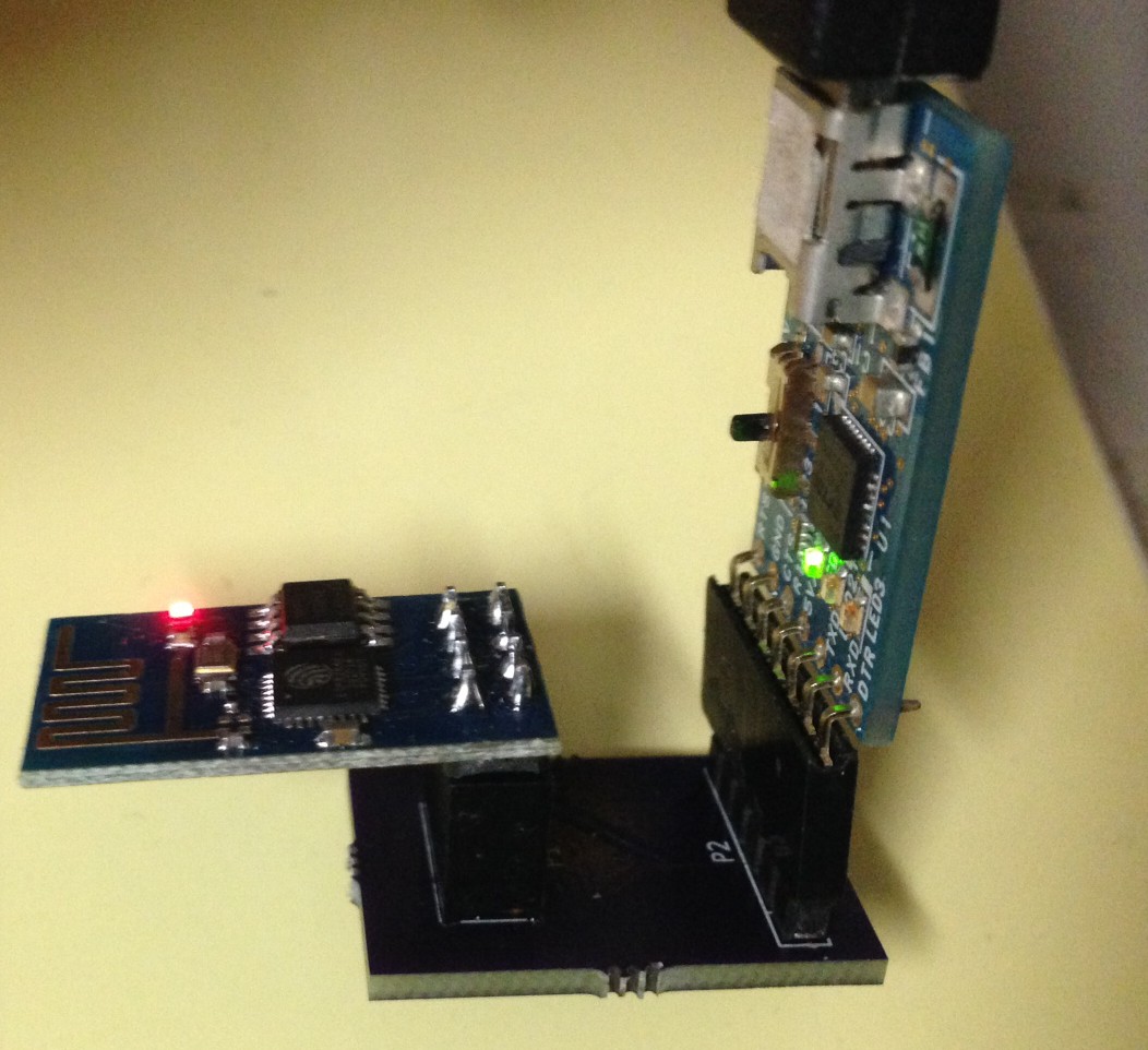
I decided I wanted a fabricated board for my esp8266 programmer. I’d previous made a quick board with wire wrap. So I put this design above together in Kicad. You can find the gerbers below, or if you like one drop me an email. One word of warning, the silk on these boards is wrong (it’s on the wrong side!). So if you do decide to build this be careful sticking the connectors on. You can also find all the files on github.
Download the gerbers here: esp8266prog
UPDATE:
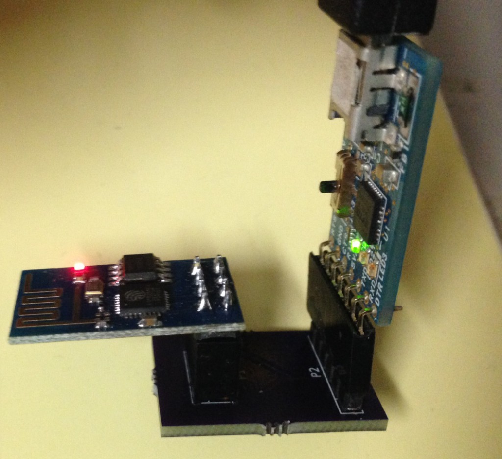
Assembled and tested, works well:
This is a continuation of my notes on the esp8266 microcontroller, you can find a complete list of my esp8266 posts here
January 18, 2015, 9:05 pm
The following short script renames the standard Kicad Gerber output filenames to those used by OSHPark and other PCB fabrication services. Put the script in the same directory as your gerbers, set execute permissions and run it. Make sure all the output files (including the drill file) are present before running the script. Let me know if you find any issues.
#!/bin/bash
front=`ls  *-F_Cu.gbr`
projname=`basename $front \-F_Cu.gbr`

mv *-F_Cu.gbr $projname.GTL
mv *-B_Cu.gbr $projname.GBL
mv *-F_Mask.gbr $projname.GTS
mv *-B_Mask.gbr $projname.GBS
mv *-F_SilkS.gbr $projname.GTO
mv *-B_SilkS.gbr $projname.GBO
mv *-Edge_Cuts.gbr $projname.GKO
mv *.drl $projname.XLN
 RSS
RSS