Singular Genomics Systems
UPDATE: If you’re interested in Singular, you should probably take a look at my review of their S-1.
Company
Singular Genomics Systems was founded in 2016. Pitchbook lists them as having raise 45.5MUSD and as being at Series B. They list Coatue Management, Domain Associates, F-Prime Capital, Revelation Partners and Arch Ventures [1] as investors [3]. They are a member of JLabs [2]. There appear to be ~60 employees listed on LinkedIn.
Technology
It appears that Singular Genomics have license technology from Jingyue Ju’s lab [4]. Jingyue Ju’s lab has generated a huge amount of IP around various approaches to DNA sequencing, so this doesn’t really narrow things down very much.
Singular’s patents also describe two different optical sequencing approaches. One is a single molecule “real time” sequencing approach (the closest similar commercial platform would be PacBio). The other is a ensemble approach (with an example showing amplified DNA on beads). I’ll briefly review these two patents below. But the main takeaway is that they appear to be working on a optical approach. I suspect it’s slightly more likely that they are working on an ensemble approach (as these are more common, and easier to get working).
The ensemble approach also shows the closest to what could be real data. So let’s look at this first:
Ensemble Approach
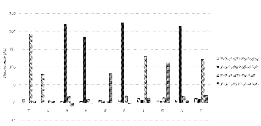
The above figure from [6] shows one innovation they describe on the basic sequencing-by-synthesis approach. Essentially what they’re suggesting is that after flowing in your standard labelled reversible terminators you flow in a “chasing mix”. This chasing mix is a set of all 4 nucleotides, with reversible terminators, but no labels. What this means is that you give all the strands a second chance to incorporate a nucleotide. This “second chance” doesn’t give you any more signal. But it does hopefully mean that unextended strands are kept “in step”.
So called “phasing” (strands failing to incorporate a base, and getting out of step) is a major source of error in sequencing-by-synthesis. I guess the idea here, is that an unlabelled nucleotide might incorporate with better efficiency than an labelled one.
Beyond this, the patent discusses methods of speeding up imaging, potentially by taking images during the “chasing step”. This is interesting in the sense that were otherwise the imaging time would be wasted, you can use it here to help extend unextended strands, without otherwise altering the signal.
The graph above shows the first 10 cycles of a fragment of PhiX. To properly understand this data it would need normalization, but there doesn’t seem to be much in the way of phasing. This work appears to have been preformed on beads. This seems to suggest that they have something up and running. Unfortunately it doesn’t tell us much about their proposed amplification/cluster/polony generation approach. I’d guess they are using a bead based platform to evaluate the chemistry and have other ideas around amplification. But it’s also possible that they are designing a bead based platform (like Ion Torrent/454).
Single Molecule Approach
Another patent [5] discusses a single molecule approach. In this approach they’re watching a polymerase incorporate nucleotides in realtime. Here they’re suggesting detection through FRET one option appears to be have a couple of FRET acceptor/donor sites on the polymerase. As the polymerase incorporates a nucleotide a conformational change occurs and your get a FRET. You also use a label on the nucleotide to then observe incorporation using FRET.
The paper suggests observation via grating style TIRF is desirable. Where the grating could be incorporated into the flowcell. There are a few other bits and pieces of interest in the patent, such as attachment methods, but nothing that looked like an experimental setup or data to me.
Overall these patents don’t give a clear picture of where Singular Genomics is heading. It seems that the approach is likely optical, and I suspect not single molecule based on the lack of experimental data. Will be interesting to see how things develop!
Notes
[1] https://www.archventure.com/portfolio/
[2] https://jlabs.jnjinnovation.com/sites/jlabs/files/JLABSPortfolioSocial.pdf
[3] https://pitchbook.com/profiles/company/226128-25#investors
[4] https://www.cbinsights.com/company/singular-genomics
[5] Single molecule approach: https://patents.google.com/patent/US20180258472A1
[6] http://www.freepatentsonline.com/y2020/0102609.html
In order to decrease SBS cycle times, in embodiments of the present disclosure the identity of distinguishable, blocked dNTP analogue incorporated into the labeled, blocked extension product(s) generated in the sequencing reaction of such cycle is assessed while the sequencing reaction is running, i.e., before the chasing reaction is initiated. In other embodiments, such assessment is conducted during the chasing reaction. In embodiments, such assessment is conducted about less than 60 seconds before termination of the sequencing reaction, about less than 60 seconds before initiation of the chasing reaction, about less than 300 seconds after initiation of the chasing reaction, or about less than 60 to about less than 10 seconds before termination of the chasing reaction. In embodiments, such assessment is conducted substantially simultaneously with initiation of the chasing reaction. In embodiments, such assessment is conducted at the conclusion of or after the chasing reaction.
chasing conditions (i.e., conditions under which an unlabeled, blocked dNTP analogue species can be incorporated into a primed template DNA molecule that was not extended to include a distinguishable, blocked dNTP analogue species), thereby forming the unlabeled, blocked extension product(s).
DNA Sequencing with Simultaneous Imaging and Chase Steps
Provided here is an example of the embodiment of a sequencing-by-synthesis method where the DNA bases were identified during the chase step. In this example, identical DNA fragments derived from the PhiX 174 genome were immobilized on 1 micron beads. The beads were tethered to a glass coverslip which was part of a flow cell. All necessary reagents for SBS were sequentially delivered into the flow cell. At first, four distinguishable, blocked dNTP analogues were presented into the flow cell. Each dNTP was labeled with a different fluorophore as follows: dCTP-Bodipy, dTTP-R6G, dATP-AF568, dGTP-AF647. A sequencing polymerase was used to incorporate these dNTPs into the complementary strand. A small volume of buffer was then used to remove any excess dye-labeled, blocked dNTPs. As a second step, dark, blocked dNTPs were introduced into the flow cell. During this second step, a set of four images was taken, one for each of the colors corresponding to each dye-labeled dNTP, while the dark dNTPs continued to be incorporated into any unextended DNA templates on the bead. The images were obtained using a Nikon microscope, with a 20×0.75 NA objective, and standard filter sets corresponding to each of the dyes. Note that the images were taken simultaneously with the chasing step, at a temperature of 60° C., demonstrating the compatibility of the two processes in terms of reaction conditions. The excess dark, blocked dNTPs were then washed out and a deprotection reagent was brought in. This reagent cleaved the blocking group and the dye from the incorporated dNTPs. The cycle was then repeated as many times as desirable. The results from the first 10 cycles obtained using this method are shown in FIG. 1. Each bar represents the fluorescent signal from the corresponding base. Spectral cross-talk correction, which compensates for the spectral bleed through from one emission channel into another, was applied to these data. No additional corrections have been applied. We have shown sequencing read lengths of >75 bases in this manner.
http://www.freepatentsonline.com/y2019/0077726.html
http://www.freepatentsonline.com/y2020/0102609.html
http://www.freepatentsonline.com/y2019/0352508.html
https://www.indeed.com/cmp/Singular-Genomics-1/reviews
 RSS
RSS