Laser CNC from Bluray parts
DISCLAIMER: Lasers are dangerous, act with caution. If you do, use laser safety goggles!
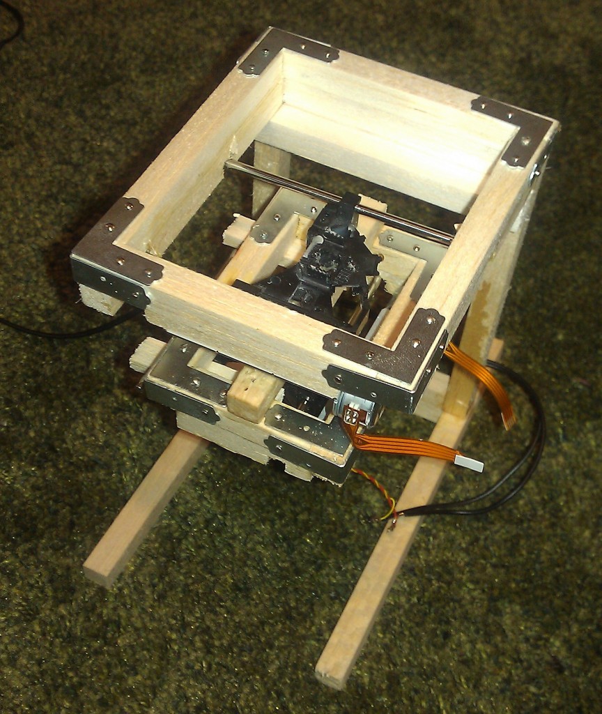
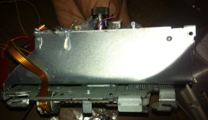
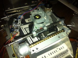
I’ve been playing with a Bluray laser, and attempting to build a CNC laser cutter. This is my proof of concept. I’ve built a stage from 2 DVD drives. These are the steppers used to control the motion of the laser as it scans across the disc.
They are mounted directly on top of each other and attached with copious amounts of glue!
The laser used is a Bluray laser from a Panasonic BDR 207 drive. This was probably the wrong choice as it’s a 3.8mm module.
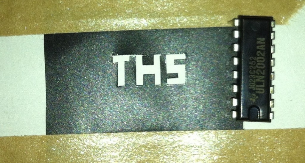
Both steppers are controlled by an Arduino using a ULN2003. The steppers seem to be at their limit and I don’t think they could push around much more weight. This maybe due to the stepper driver, or just because they’re not really designed to move much weight around. I also can’t drive both steppers simultaneously, possibly because of the wall wart power supply I’m currently using… Anyway that means no diagonal motion right now.
Anyway, even with all it’s faults I’m pretty happy with it as a proof of concept! Here it is cutting its way through some plastic:
And here’s the result:
Total component cost is around 100USD. After hacking the above rig together, I then when on to build a slightly more robust system:
Here’s the second rig in action:
If I continue this project there are a number of improvements to be made:
Different stepper driver (I’ll probably just get an EasyDriver from sparkfun).
Different steppers/mechanical components (possibly harvest the components from scanners next time, as the DVD parts give a very small work area).
Properly machine everything (even though it means less glue gun use 🙁 ).
I’d use the laser from a Panasonic S06J drive, it’s a 5.6mm laser, and slightly higher power than the BDR 207.
Code
const int motorAPin1 =4;
const int motorAPin2 =5;
const int motorAPin3 =6;
const int motorAPin4 =7;

const int motorBPin1 =8;
const int motorBPin2 =9;
const int motorBPin3 =10;
const int motorBPin4 =11;

void setup() {
  // initialize the digital pin as an output.
  // Pin 13 has an LED connected on most Arduino boards:
  pinMode(motorAPin1, OUTPUT);
  pinMode(motorAPin2, OUTPUT);
  pinMode(motorAPin3, OUTPUT);
  pinMode(motorAPin4, OUTPUT);

  pinMode(motorBPin1, OUTPUT);
  pinMode(motorBPin2, OUTPUT);
  pinMode(motorBPin3, OUTPUT);
  pinMode(motorBPin4, OUTPUT);

  //ar(30);
  //assbr(30);

}

void stepFwd(int motorPin1,int motorPin2,int motorPin3,int motorPin4) {
  int motorDelay=50;
  digitalWrite(motorPin1, HIGH);
  digitalWrite(motorPin2, LOW);
  digitalWrite(motorPin3, HIGH);
  digitalWrite(motorPin4, LOW);
  delay(motorDelay);

  digitalWrite(motorPin1, HIGH);
  digitalWrite(motorPin2, LOW);
  digitalWrite(motorPin3, HIGH);
  digitalWrite(motorPin4, HIGH);
  delay(motorDelay);

  digitalWrite(motorPin1, HIGH);
  digitalWrite(motorPin2, LOW);
  digitalWrite(motorPin3, LOW);
  digitalWrite(motorPin4, HIGH);
  delay(motorDelay);

  digitalWrite(motorPin1, HIGH);
  digitalWrite(motorPin2, HIGH);
  digitalWrite(motorPin3, LOW);
  digitalWrite(motorPin4, HIGH);
  delay(motorDelay);

  digitalWrite(motorPin1, LOW);
  digitalWrite(motorPin2, HIGH);
  digitalWrite(motorPin3, LOW);
  digitalWrite(motorPin4, HIGH);
  delay(motorDelay);

  digitalWrite(motorPin1, LOW);
  digitalWrite(motorPin2, HIGH);
  digitalWrite(motorPin3, HIGH);
  digitalWrite(motorPin4, HIGH);
  delay(motorDelay);

  digitalWrite(motorPin1, LOW);
  digitalWrite(motorPin2, HIGH);
  digitalWrite(motorPin3, HIGH);
  digitalWrite(motorPin4, LOW);
  delay(motorDelay);

  digitalWrite(motorPin1, HIGH);
  digitalWrite(motorPin2, HIGH);
  digitalWrite(motorPin3, HIGH);
  digitalWrite(motorPin4, LOW);
  delay(motorDelay);
}

void stepRev(int motorPin1,int motorPin2,int motorPin3,int motorPin4) {
  int motorDelay=50;
  digitalWrite(motorPin1, HIGH);
  digitalWrite(motorPin2, HIGH);
  digitalWrite(motorPin3, HIGH);
  digitalWrite(motorPin4, LOW);
  delay(motorDelay);

  digitalWrite(motorPin1, LOW);
  digitalWrite(motorPin2, HIGH);
  digitalWrite(motorPin3, HIGH);
  digitalWrite(motorPin4, LOW);
  delay(motorDelay);

  digitalWrite(motorPin1, LOW);
  digitalWrite(motorPin2, HIGH);
  digitalWrite(motorPin3, HIGH);
  digitalWrite(motorPin4, HIGH);
  delay(motorDelay);

  digitalWrite(motorPin1, LOW);
  digitalWrite(motorPin2, HIGH);
  digitalWrite(motorPin3, LOW);
  digitalWrite(motorPin4, HIGH);
  delay(motorDelay);

  digitalWrite(motorPin1, HIGH);
  digitalWrite(motorPin2, HIGH);
  digitalWrite(motorPin3, LOW);
  digitalWrite(motorPin4, HIGH);
  delay(motorDelay);

  digitalWrite(motorPin1, HIGH);
  digitalWrite(motorPin2, LOW);
  digitalWrite(motorPin3, LOW);
  digitalWrite(motorPin4, HIGH);
  delay(motorDelay);

  digitalWrite(motorPin1, HIGH);
  digitalWrite(motorPin2, LOW);
  digitalWrite(motorPin3, HIGH);
  digitalWrite(motorPin4, HIGH);
  delay(motorDelay);

  digitalWrite(motorPin1, HIGH);
  digitalWrite(motorPin2, LOW);
  digitalWrite(motorPin3, HIGH);
  digitalWrite(motorPin4, LOW);
  delay(motorDelay);
}

void stop(int motorPin1,int motorPin2,int motorPin3,int motorPin4) {

  digitalWrite(motorPin1, LOW);
  digitalWrite(motorPin2, LOW);
  digitalWrite(motorPin3, LOW);
  digitalWrite(motorPin4, LOW);
}


void af(int nm) {
  for(int n=0;n<nm;n++) { stepFwd(motorAPin1,motorAPin2,motorAPin3,motorAPin4); } stop(motorAPin1,motorAPin2,motorAPin3,motorAPin4);
}

void ar(int nm) {
  for(int n=0;n<nm;n++) { stepRev(motorAPin1,motorAPin2,motorAPin3,motorAPin4); } stop(motorAPin1,motorAPin2,motorAPin3,motorAPin4);
}

void bf(int nm) {
  for(int n=0;n<nm;n++) { stepFwd(motorBPin1,motorBPin2,motorBPin3,motorBPin4); } stop(motorBPin1,motorBPin2,motorBPin3,motorBPin4);
}

void br(int nm) {
  for(int n=0;n<nm;n++) { stepRev(motorBPin1,motorBPin2,motorBPin3,motorBPin4); } stop(motorBPin1,motorBPin2,motorBPin3,motorBPin4);
}

void drawT() {
  bf(6);
  af(2);
  br(2);
  af(8);
  br(2);
  ar(8);
  br(2);
  ar(2);
}

void drawH() {
  bf(2);
  af(4);
  bf(4);
  ar(4);
  bf(2);
  af(10);
  br(2);
  ar(4);
  br(4);
  af(4);
  br(2);
  ar(10);
}

void drawS() {
  bf(6);
  af(2);
  br(4);
  af(2);
  bf(4);
  af(6);
  br(6);
  ar(2);
  bf(4);
  ar(2);
  br(4);
  ar(6);
}

void loop() {

  for(int n=0;n<3;n++) drawT();
  bf(8);
  for(int n=0;n<3;n++) drawH();
  bf(10);
  for(int n=0;n<3;n++) drawS();
  //br(18);
  for(;;);

//  for(int n=0;n<20;n++) { stepFwd(motorAPin1,motorAPin2,motorAPin3,motorAPin4); } stop(motorAPin1,motorAPin2,motorAPin3,motorAPin4);

//  for(int n=0;n<25;n++) { stepFwd(motorBPin1,motorBPin2,motorBPin3,motorBPin4); } stop(motorBPin1,motorBPin2,motorBPin3,motorBPin4);

//  for(int n=0;n<20;n++) { stepRev(motorAPin1,motorAPin2,motorAPin3,motorAPin4); } stop(motorAPin1,motorAPin2,motorAPin3,motorAPin4);

//  for(int n=0;n<25;n++) { stepRev(motorBPin1,motorBPin2,motorBPin3,motorBPin4); } stop(motorBPin1,motorBPin2,motorBPin3,motorBPin4);
}


[…] on the messy hack. That was the previous version of my Bluray laser cutter, I decided to make a slightly more solid […]
Nice, now see if it will photoetch a sensitive board for direct to PCB printing.
I did wonder about using ULN2003’s as my stepper drivers kept failing.
One thing I learned the hard way is that mechanical alignment is a pain.
Best to add a focus adjustment to compensate for sled irregularities, and have a positional feedback that applies a bias on the focus to keep it aligned over the entire build area like adjusting a CRT.
Might also work if you used a PS3 diode in line with the burner as these have visible light and a sensor so you can read current laser intensity and prevent thermal runaway (guess how I found that out)
-A
Great idea, but your arduino code is very messy and could do with a rewrite.
I can only imagine how long it took you to code the stepFwd and stepRev functions.
Your code for stepFwd() and the like would work just as well, and more efficiently if you change it to:
void stepDir(int direction, int motorPin1,int motorPin2,int motorPin3,int motorPin4){
/*
direction: 0 for forward, anything else for reverse
*/
int motorDelay=50, s, d, i;
switch(direction)
{
case 0: // 0 = Forward
s = 0;
d = 1;
break;
default: // anything else: backward
s = 7;
d = -1;
break;
}
for(i = 0; i < 8; i++)
{
switch(s)
{
case 0:
digitalWrite(motorPin1, HIGH);
digitalWrite(motorPin2, LOW);
digitalWrite(motorPin3, HIGH);
digitalWrite(motorPin4, LOW);
break;
case 1:
digitalWrite(motorPin1, HIGH);
digitalWrite(motorPin2, LOW);
digitalWrite(motorPin3, HIGH);
digitalWrite(motorPin4, HIGH);
break;
case 2:
digitalWrite(motorPin1, HIGH);
digitalWrite(motorPin2, LOW);
digitalWrite(motorPin3, LOW);
digitalWrite(motorPin4, HIGH);
break;
case 3:
digitalWrite(motorPin1, HIGH);
digitalWrite(motorPin2, HIGH);
digitalWrite(motorPin3, LOW);
digitalWrite(motorPin4, HIGH);
break;
case 4:
digitalWrite(motorPin1, LOW);
digitalWrite(motorPin2, HIGH);
digitalWrite(motorPin3, LOW);
digitalWrite(motorPin4, HIGH);
case 5:
digitalWrite(motorPin1, LOW);
digitalWrite(motorPin2, HIGH);
digitalWrite(motorPin3, HIGH);
digitalWrite(motorPin4, HIGH);
break;
case 6:
digitalWrite(motorPin1, LOW);
digitalWrite(motorPin2, HIGH);
digitalWrite(motorPin3, HIGH);
digitalWrite(motorPin4, LOW);
break;
case 7:
digitalWrite(motorPin1, HIGH);
digitalWrite(motorPin2, HIGH);
digitalWrite(motorPin3, HIGH);
digitalWrite(motorPin4, LOW);
break;
default:
break;
}
delay(motorDelay);
s += d;
}
}
void stepFwd(int motorPin1,int motorPin2,int motorPin3,int motorPin4)
{
stepDir(0, motorPin1, motorPin2, motorPin3, motorPin4);
}
void stepRev(int motorPin1,int motorPin2,int motorPin3,int motorPin4)
{
stepDir(-1, motorPin1, motorPin2, motorPin3, motorPin4);
}
Thanks! Yes, the code is very messy at the moment. In a later update, and probably after switching to an EasyDriver, I’d like to have a bash at processing GCode. Thanks for the refactoring suggestion!
Yes, I really want t do something with PCBs. I’ve looked around a little for information on the light sensors, but I’ve not been able to find a pinout yet. The sleds are amazing pieces of electronics though, some include their own /tiny/ steppers for focusing. I’ve been wondering if the same setup could be used for melting low temperature solder cream. That would be an interesting possibility.
Well done. Now I suggest you to buy a simple PrintrBot and replace the plastic-melting head with your laser unit. If you add an external tool that distributes some plastic powder between shifts in the Z axis, you have a 3D sintering machine!
You are not allowed to sell components and assembled parts (some patents are still valid), but you can freely give instruction manuals and people can buy what they need and build it. In the meanwhile, you get experience and in 2-3 years, when the patents expire (it’s really close), you have a working product you can immediately sell.
I’m serious, contact the people of PrintrBot and merge your product with theirs: you can only publish build instructions (people will print the parts…) but it would be useful anyway: the early adopters will beta test it.
Hi Nava, awesome blog here! I’m the guy that wrote that horrible code and made the weird circuit a couple of years back for controlling a bipolar stepper with an Arduino using an ULN Darlington Array. I have to admit, this has been a source of (almost) embarrasment for me ever since. The reason I picked the ULNs was because I had no H-bridges on hand (such as SN754410 or L298 or similar) and wanted to have the thing move no matter what, tonight! This was more like an excersice in MacGuyvering than finding a good solution.The actual proper way to drive a bipolar stepper is of course with an H-bridge driver ICs. They are only slightly more expensive and just slightly less popular than ULNs. The circuit you are using was designed around a concept of wasting 1/2 of the energy on those pullup resistors – not really a good approach for a real life situation, like driving stages of a CNC rig.
All that said, kudos to you for taking a bad circuit and a bad software and making the best of it I have seen on the Net so far! 🙂
haha thanks Nick! I purchased an easydriver in the end (but never got round to using it). The hack was good fun! Yes if I remember correctly the driver board could get pretty hot, certainly not an efficient solution. 🙂 If you’re ever in Japan I owe you a beer.
hello! how did you connect the laser driver? is there ttl?
It was quite a while ago, and I don’t have the setup here. But if I remember correctly the driver took a 5V input and it effectively provides current limiting to the laser diode. I’m not sure if it’s perhaps doing anything smarter like a pulse drive.