Sputtering machine notes
Sputtering machines (also called sputter coaters) are amazing, they’re able to lay down thin films of both conductive and insulating material.
Somewhat surprisingly for such an advanced technique, sputtering has been known about for a long time, though it’s mechanism was not originally well understood.
John Strong’s excellent 1920s book “Procedures in Experimental Physics” for example includes this great diagram of a sputtering setup:
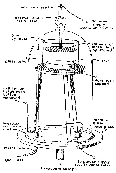
The procedure hasn’t changed much since then, and I’ll use this diagram as a reference. As you can see in the diagram the metal to be sputtered (commonly and slightly confusingly called the target) cathode is connected to a large negative voltage typically in-excess of 1000volts. The material to be coated is placed near the target. In this diagram a piece of glass is being coated with metal to make a mirror, a fairly typical application of sputtering. Behind the material to be coated is a metal plate which is grounded with respect to the negative supply.
Sputtering will not work in air, so the whole process takes place in a vacuum chamber. It is however not a particularly high vacuum, and I believe only a roughing pump is required. The process actually requires gas to be present in the chamber. Typically argon, but other noble gases or even air can be used.
In the sputtering process electrons leave the target which is negatively charged, and move toward the substrate. Very occasionally as they follow this path, they hit an atom of gas. This ionizes the gas atom. The now positively charged atom is drawn toward the target material and smashes into it. This process smashes single atoms off the target which fly out into the vacuum, eventually hitting the substrate to which they anneal.
This is the basic process. Sputtering has a number of advantages over vapor based deposition techniques (which boil a metal in a vacuum in order to eject atoms into the vacuum and then onto the substrate). And as we will see, can even be used to generate films of insulating materials.
DC Sputtering
The process described above is basic DC sputtering. While this was the original technique there is one refinement which practically all sputtering machines now use. This is to confine the electrons somewhat using a magnetron. The magnetron uses magnetic and electric fields to keep the electrons near the target.
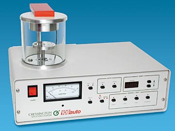
The above image shows a typical DC Magnetron sputtering machine. These typically cost a few thousand USD used. Their most common application is in coating samples prior to being imaged in an SEM. SEMs in general require samples to have a conductive outer layer.
RF Sputtering
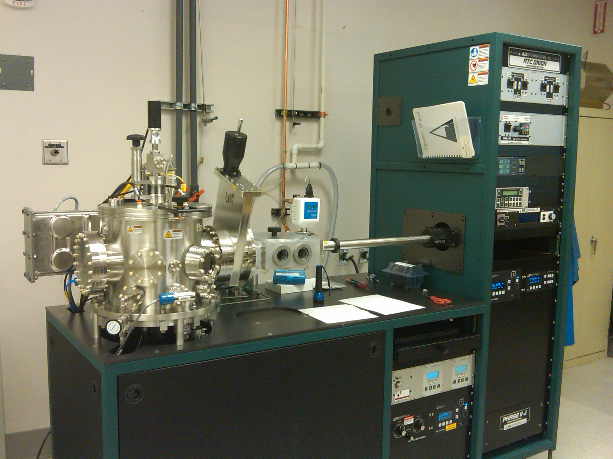
RF Magnetron Sputtering machines tend to be a bit more serious, like the one shown above. There’s no real reason that they need to be that big however. RF machines use an AC, rather than a DC voltage. Typically these systems operate at a frequency of 13.56MHz. An AC voltage means that the target wont build up any charge, allowing insulting targets to be used.
Self builds
A number of people have built their own sputtering machines from parts, notably Ben Krasnow has an excellent video on his build:
Other builds are a little more ghetto, but interesting because they often re-use microwave parts to build the magnetron: