Thanks for buying the Atari Punk Console (APC) kit. For those who have soldered before, building the kit should be straight forward. The kit contains all the parts to build the APC. In addition to these parts you'll need a soldering iron, some solder, and a pair of wire cutters. See the recommendations section for more information on recommend tools and soldering advice. This guide is also available as a youtube video (https://www.youtube.com/watch?v=ZxFor8im2Xk) which might be easier to follow!
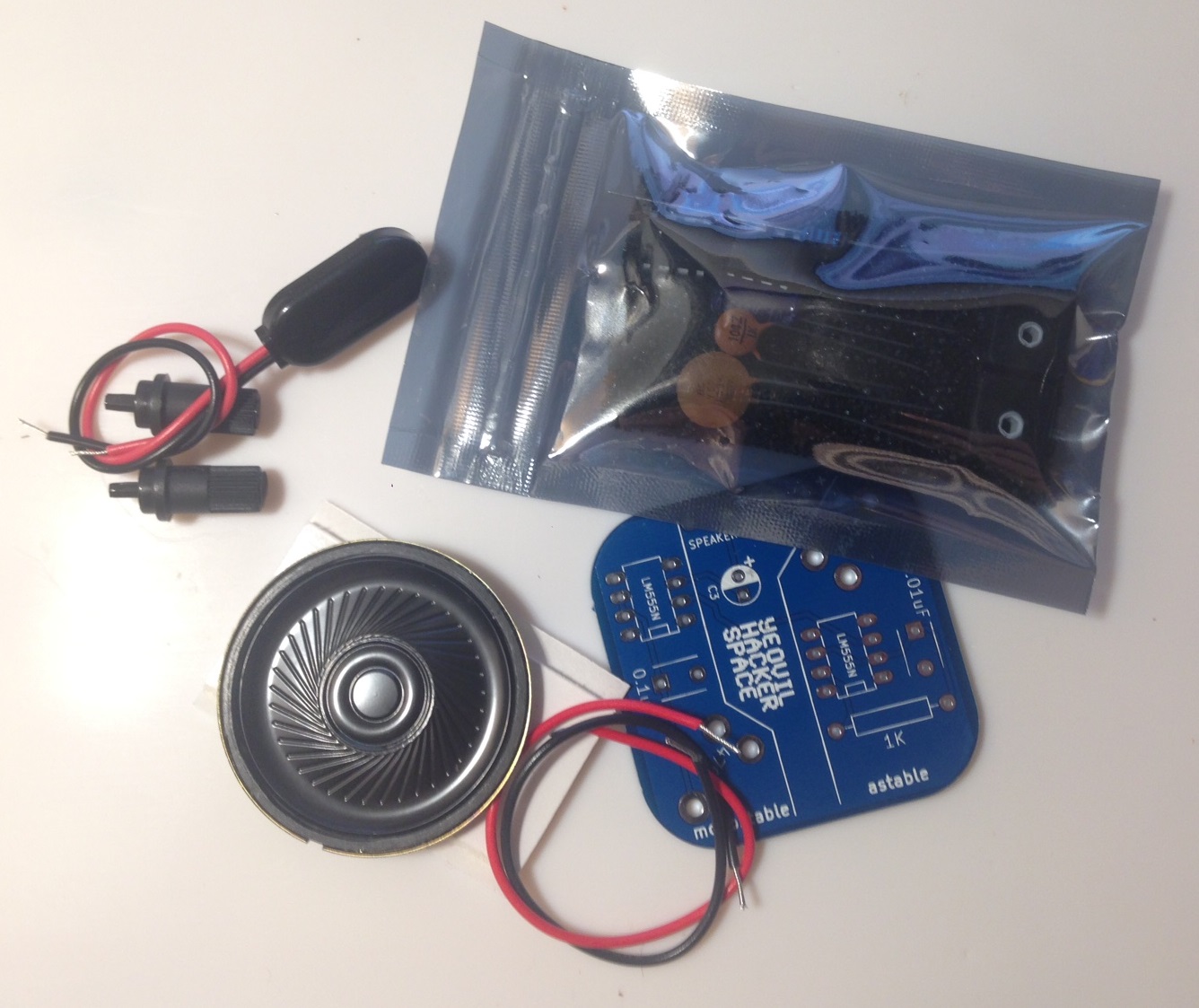
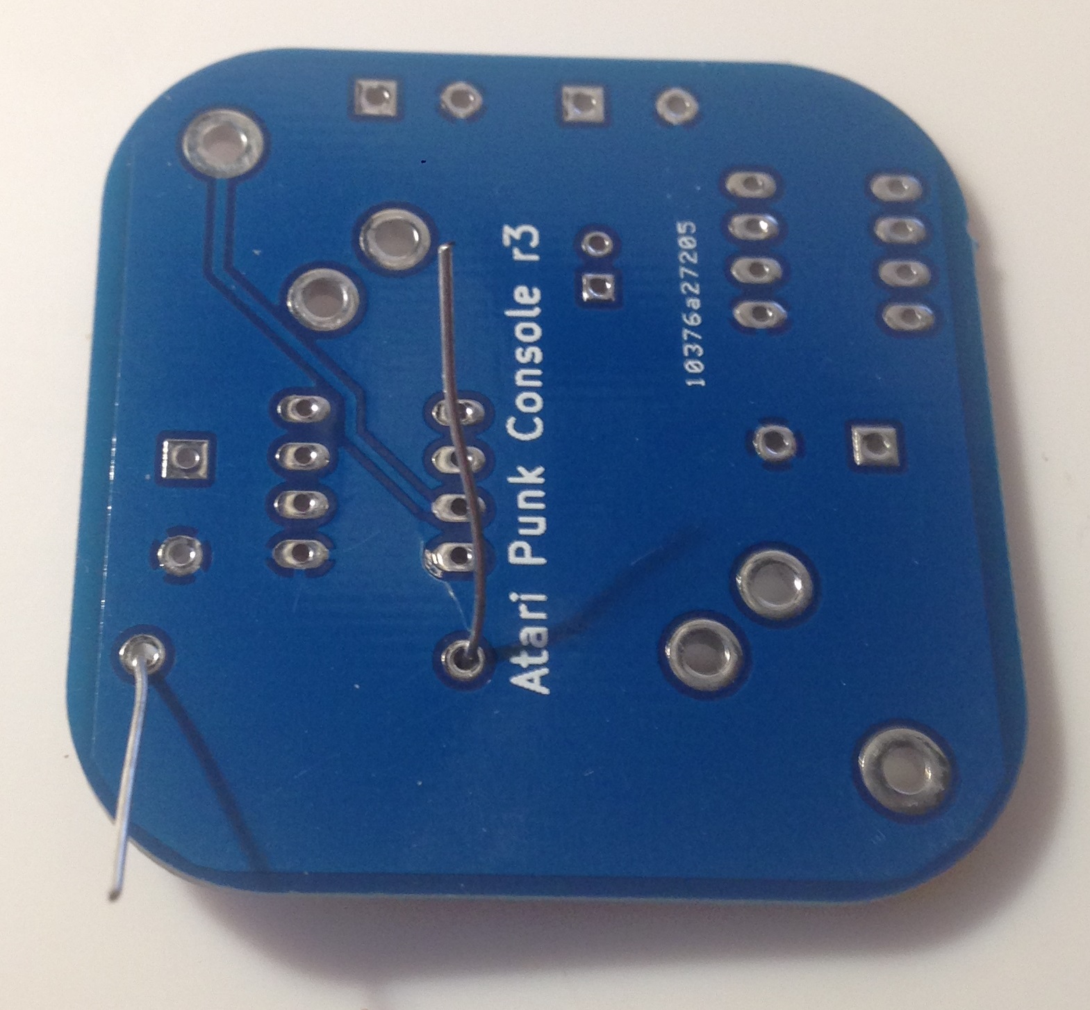
The kit should look something like this:
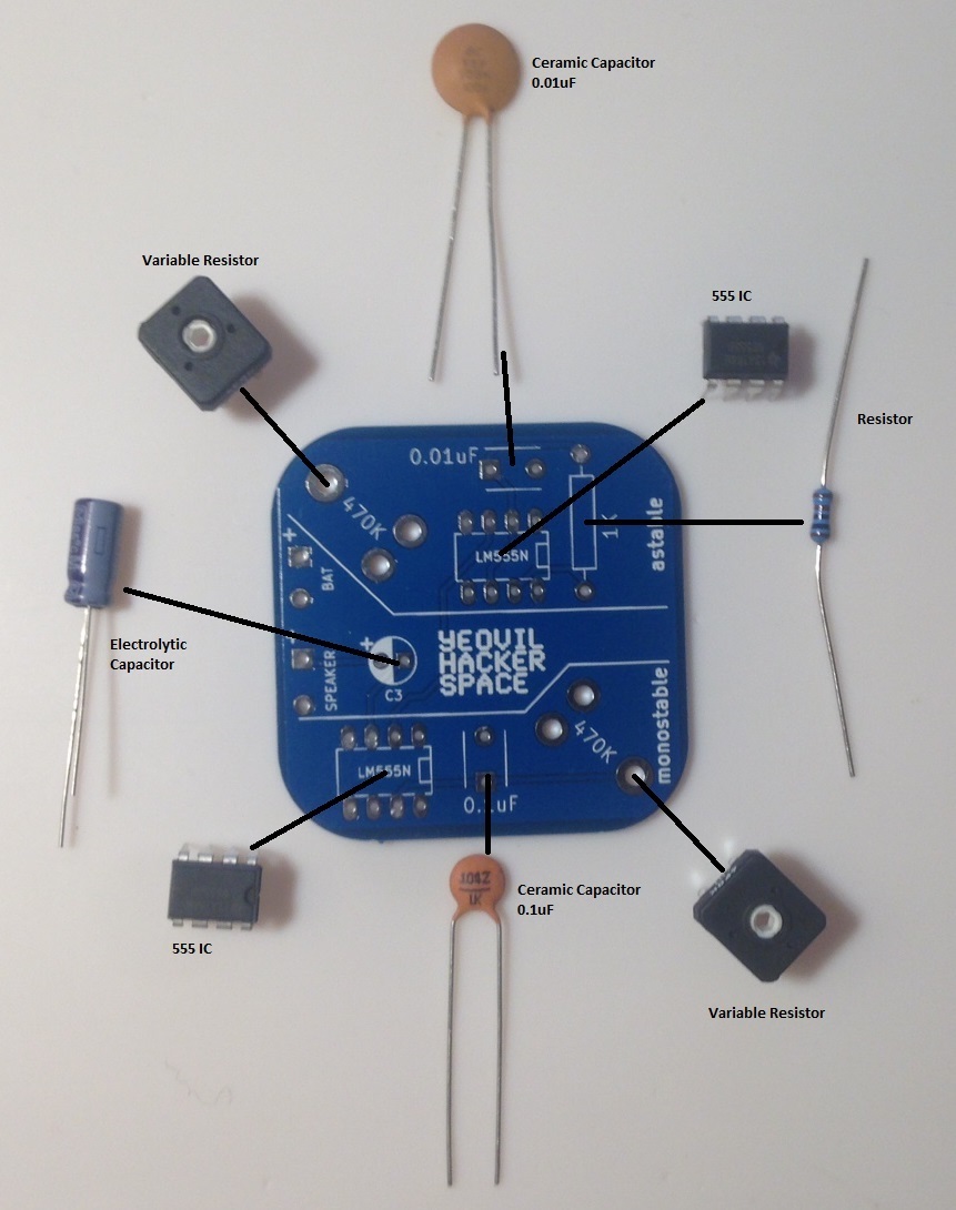
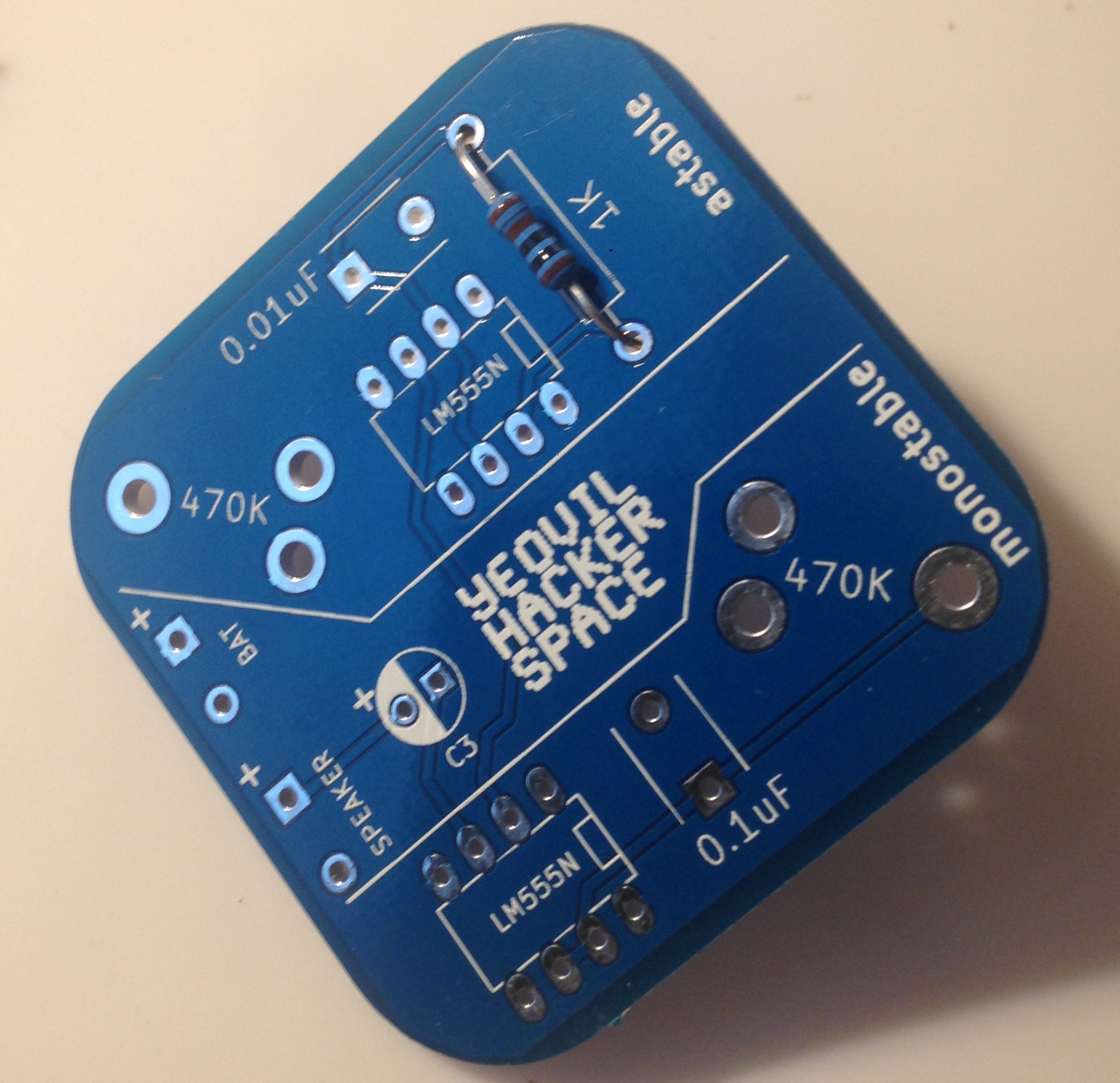
The first job is to figure out where everything goes. Open the little silver bag and examine the components. The diagram below shows where they go on the board:
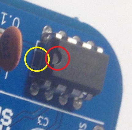
For the most part the components will only fit in one place on the board. But there are two that look very similar:
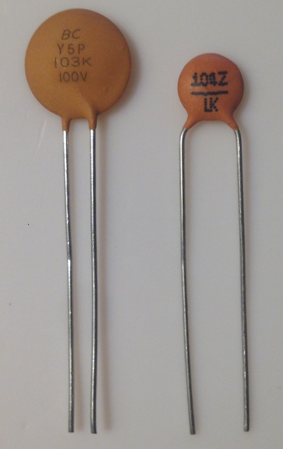
So be careful when soldering them to the board. The big one is 0.01uF (the smaller value) and the small one is 0.1uF (the bigger value).
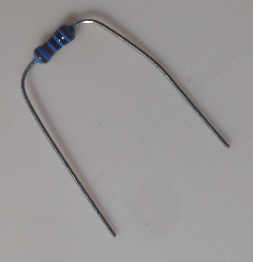
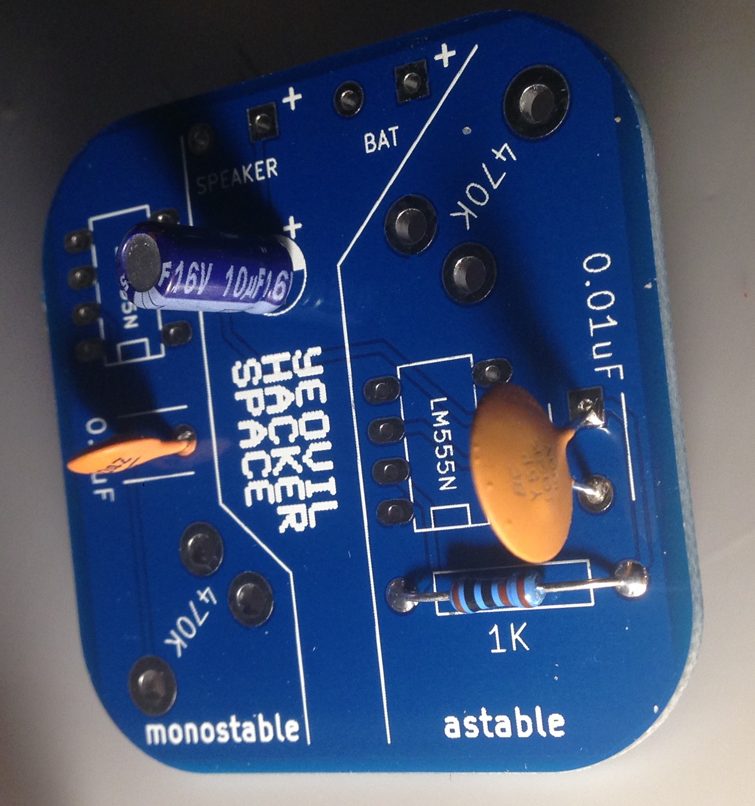
Great! That's the first component done! Now install the ceramic capacitors similarly.
When installing the electrolytic capacitor you need to be a little careful. Make sure the white "-" marking is placed AWAY from the "+" side on the board like so:
Once all the components are soldered in check over the board. Make sure everything is in the right place and that the solder joints all look shiny, that there are no gaps in the solder were you can see the pad and that the solder is attached properly to the pad and the leads.
We're almost done now! We just need to attach the battery chip and speaker.
When installing the battery clip, you might want to twist the two wires. This keeps the wire neat, but it's entirely optional!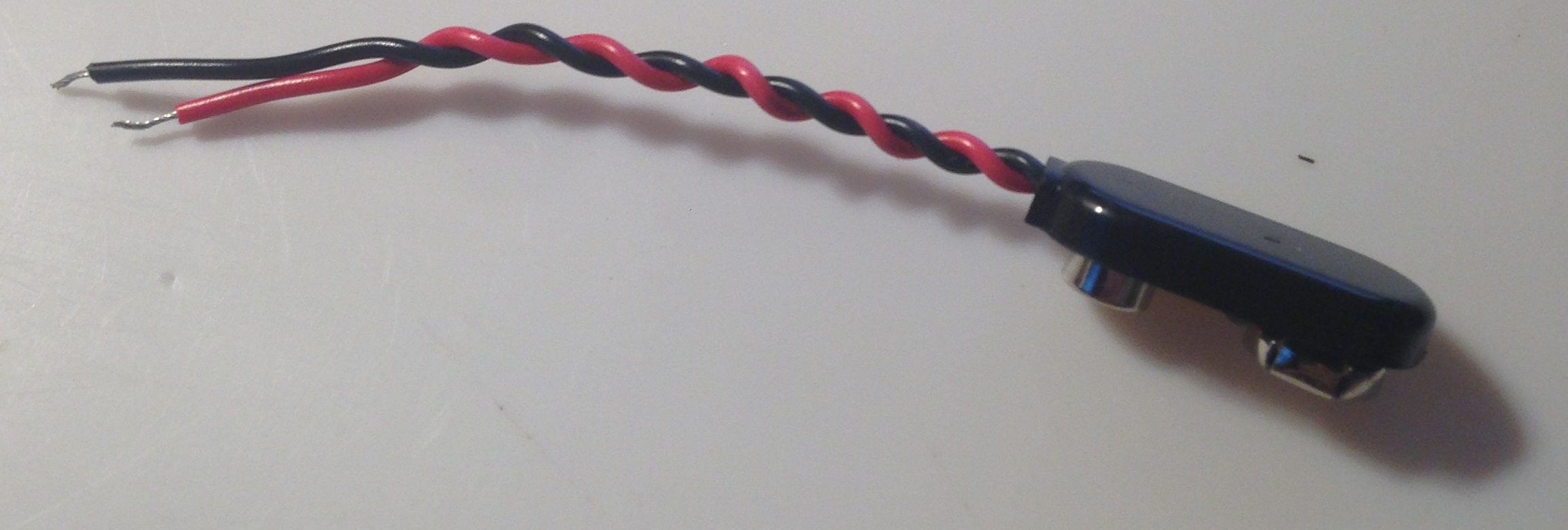
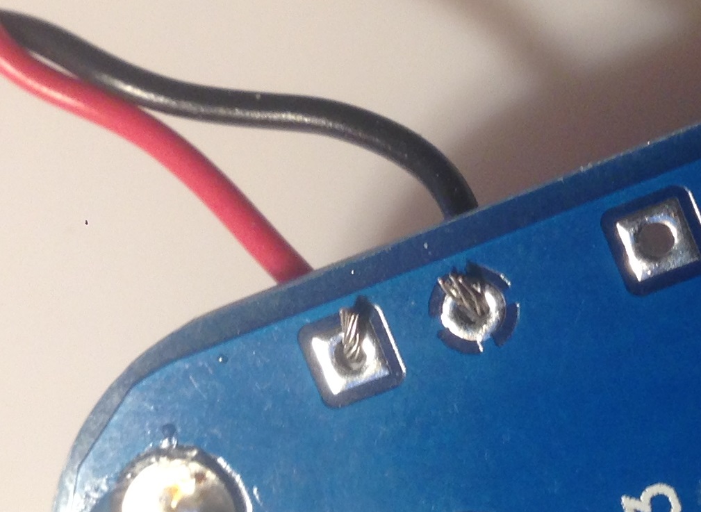
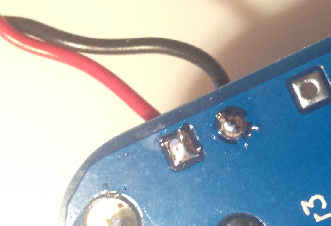
Find the two short red and black wires in the kit. As you did with the clip, solder the red wire into the hole marked "+" near the "SPEAKER" label and the black wire through the other hole. Then twist up the wires if you want to.
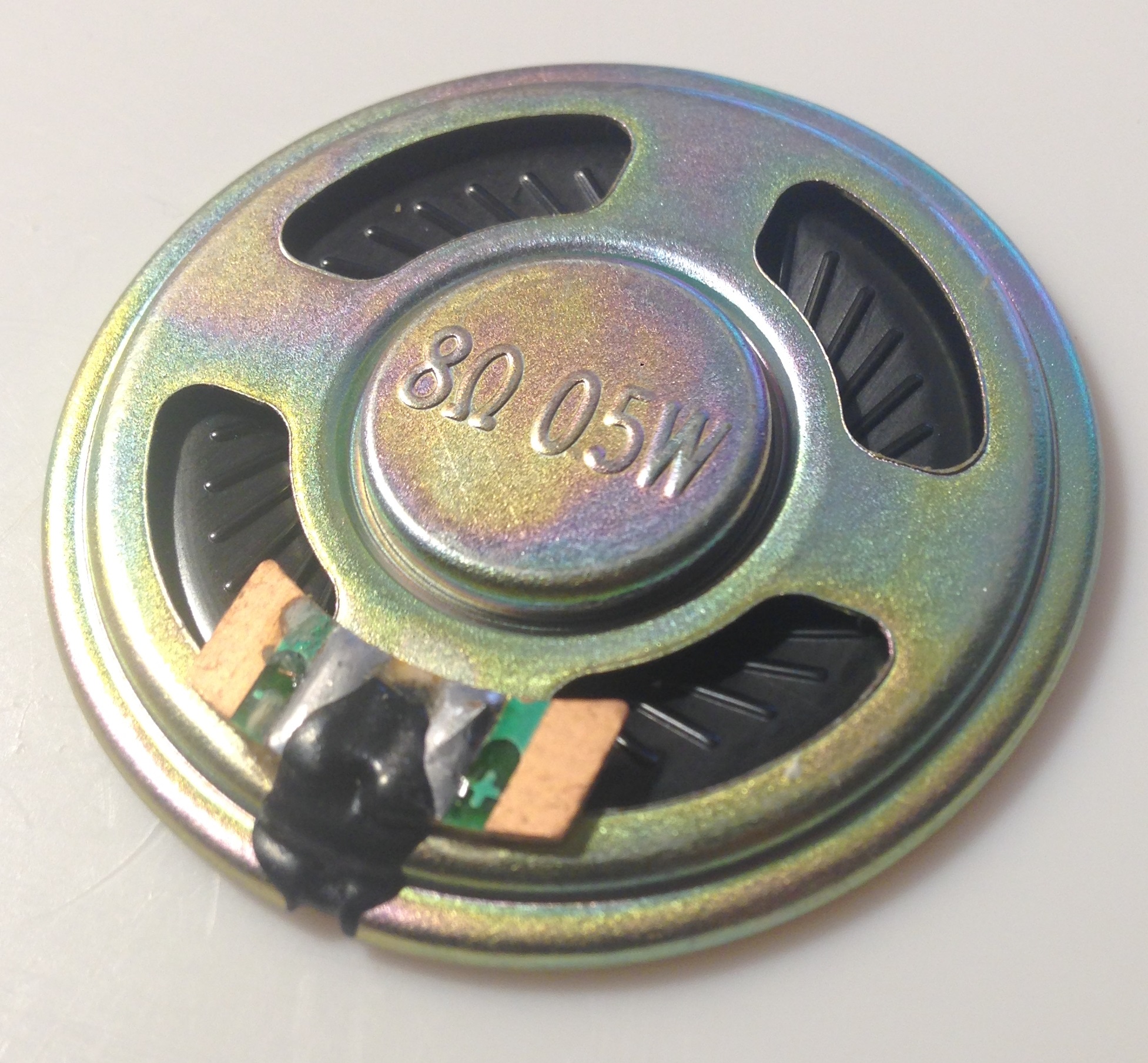
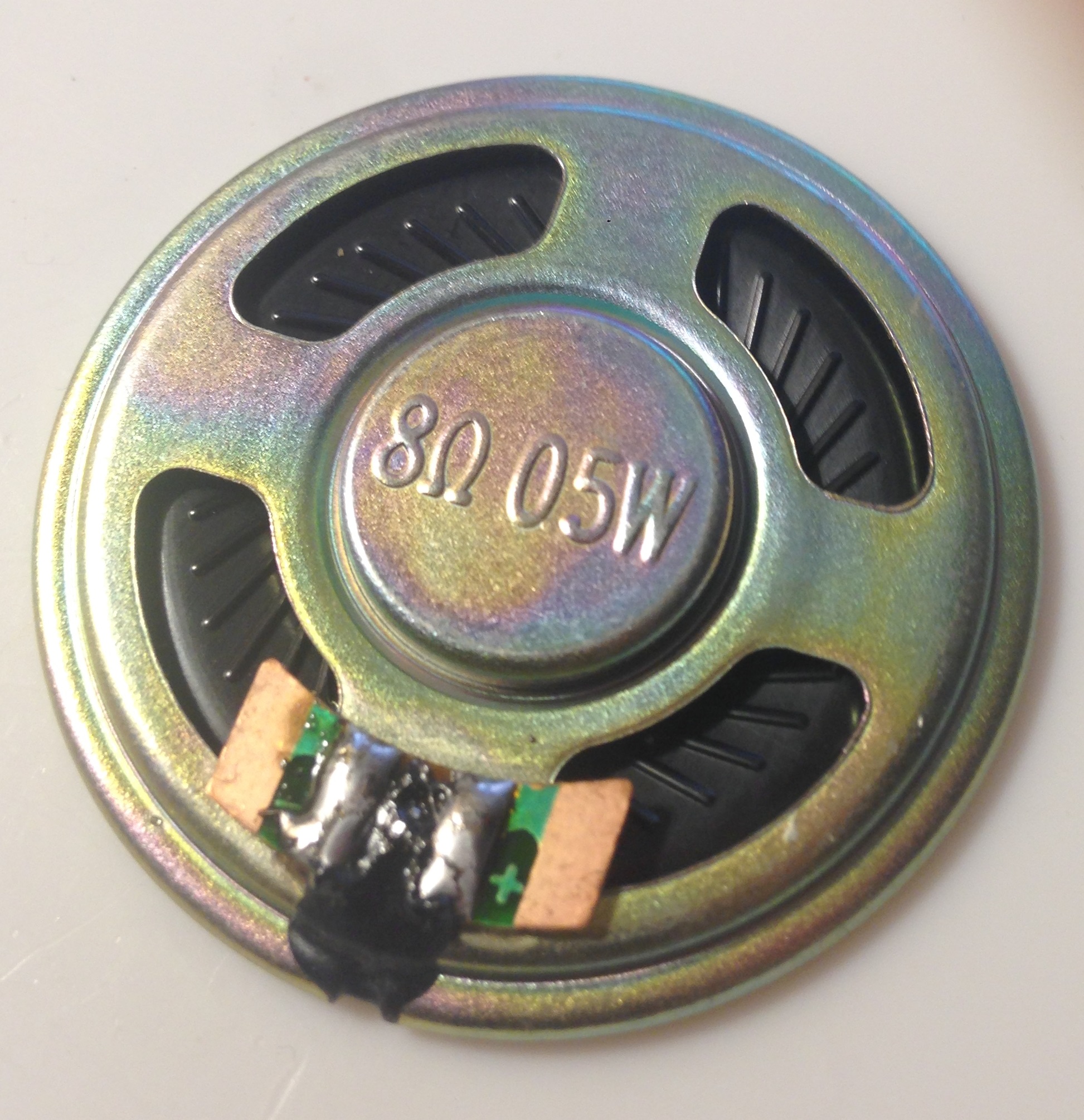
Finally we're going to attached the speaker to the cables. First add a little bit of solder to the pads on the speaker so that they're nice and shiny as shown below:
Now solder the wires to the speaker. Place the red wire against the right pad and solder it down. Make sure the pad gets nice and hot and the solder flows well, hold the wire down (using the insulation away from the iron) and remove the iron while holding everything in place while it solidifies. Do the same on the other pad with the black wire.
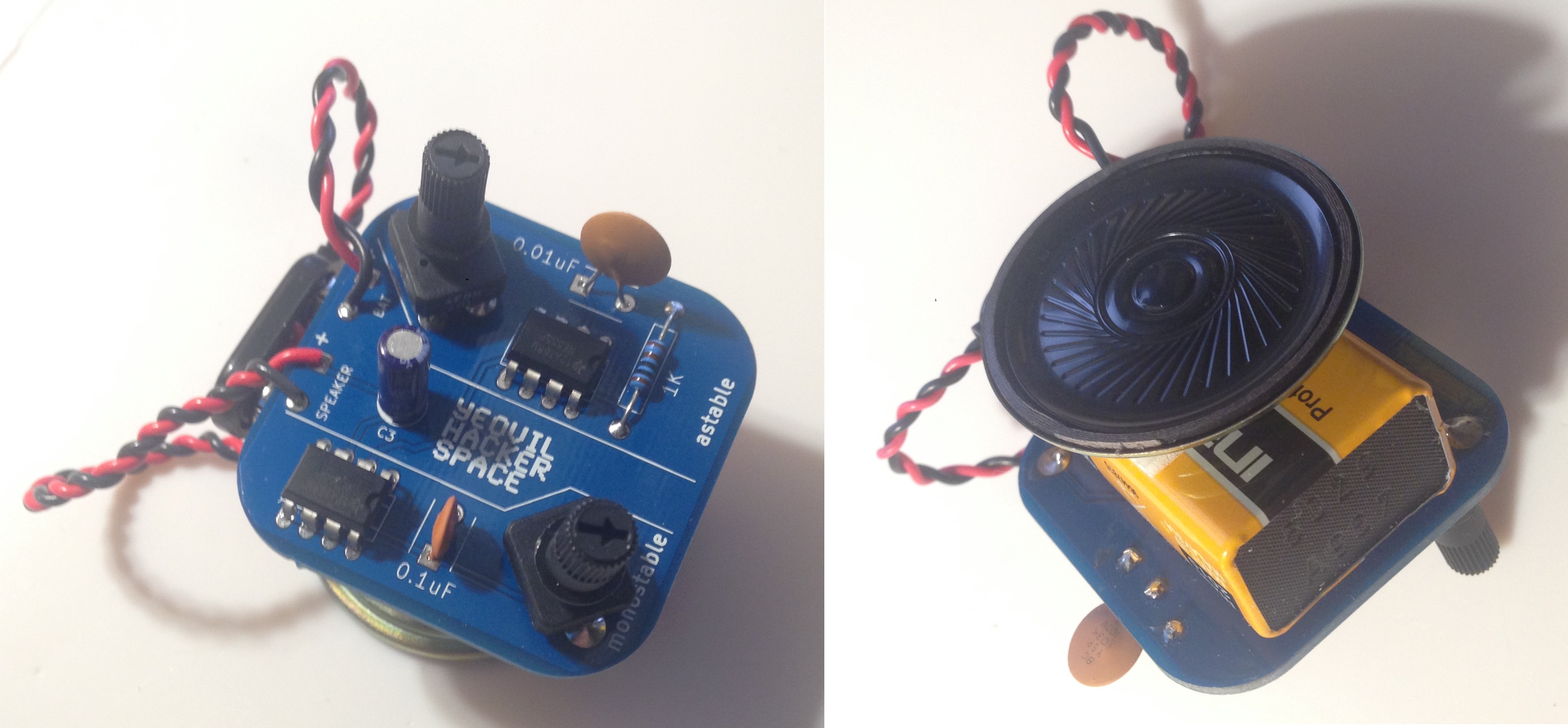
Great! That's all the soldering done! Now attach a battery and see if everything works, twist the knobs and it should start making noises! You can use the enclosed tape to hold everything together:
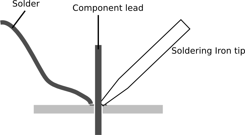
If you're already comfortable soldering you should have no issues with this kit. If not I recommend taking a look at the EEVBlog videos on the subject (https://www.youtube.com/watch?v=J5Sb21qbpEQ. Briefly heat should be applied to both the pad and the component lead as shown below. Solder should be fed into the side opposite the iron, this ensures both the lead and the pad have heated up.
I recommend a good temperature controlled soldering iron. The Hakko FX888 is a good soldering iron and available from Adafruit in the US. In the UK it's harder to get hold of (almost all the Hakkos on eBay are fake). The Aoyue soldering irons are cheap and almost as good however. Make sure you get a chisel tip for it (I'm using a T18-S9 but any small chisel tip should be fine). As for solder, I recommend leaded solder for hobbiests. Leaded solder flows better and is easier to use. There are however safety concerns you should be aware of, and for this reason you might want to use unleaded solder. I use a 0.6mm diameter leaded solder (Goot SE-06006RMA). The one other tool you'll need is a pair of wire cutters, I recommend a tool with a good flat edge (for example Hozan N-34s). However you can get away with a pair from your local pound (or dollar) store.